


35
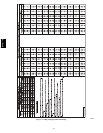
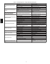
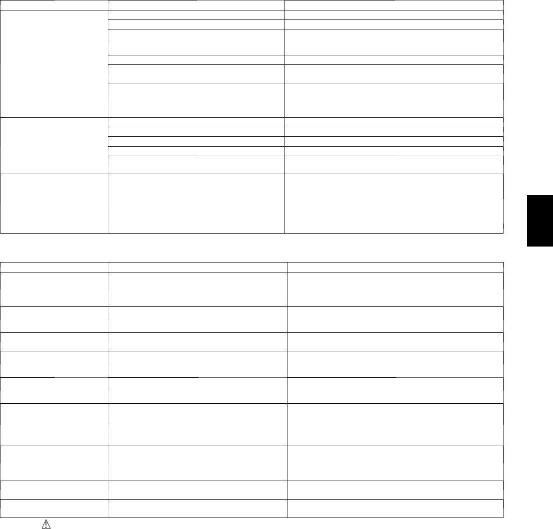
Table 12 – Troubleshooting Guide–Heating
SYMPTOM CAUSE REMEDY
Burners will not ignite
Water in gas line Drain. Install drip leg.
No power to furnace Check power supply fuses, wiring or circuit breaker.
No 24--v power supply to control circuit
Check transformer.
NOTE: Some transformers have internal over--current protection
that requires a cool--down period to reset.
Mis--wired or l oose connections Check all wi ring and wire nut connections
Misaligned spark el ectrodes
Check flame ignition and sense electrode positioning.
Adjust as necessary.
No gas at main burners
1. Check gas line for air. Purge as necessary. NOTE: After purging
gas line of air, wait at least 5 minutes for any gas to dissipate be-
fore attempting to light unit.
2. Check gas valve.
Inadequate heating
Dirt y air filter Clean or replace filter as necessary
Gas input to furnace too low Check gas pressure at manifold match with that on unit nameplate
Unit undersized for application Replace with proper unit or add additional uni t
Restricted airflow Clean or replace filter. Remove any restriction.
Limit switch cycles main burners
Check rotation of blower, temperature rise of unit. Adjust as neces-
sary.
Poor flame characteristics
Incomplete combustion results in: Aldehyde odors,
carbon monox ide, sooting flame, floati ng flame
1. Tighten all screws around burner compartment
2. Cracked heat exchanger. Replace.
3. Unit over--fired. Reduce input (change orifices or adjust gas line
or manifold press ure).
4. Check burner alignment.
5. Inspect heat exchanger for blockage. Clean as necessary.
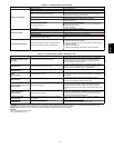
Table 13 – Troubleshooting Guide–LED Status Codes
SYMPTOM CAUSE REMEDY
No Power Hardware failure
(LED OFF)
Loss of power to control module (IGC)*.
Check 5--amp fuse son IGC*, power to unit, 24--v circuit breaker,
and transformer. Units without a 24--v circuit breaker have an
internal overload in the 24--v transformer. If the overload trips,
allow 10 minutes for automatic reset.
Limit switch faults
(LED 2 flashes)
High temperature limit switch is open.
Check the operation of the indoor (evapor ator) fan motor . Ensure
that the supply--air temperature rise is in accordance with the
range on the unit nameplate. Clean or replace filters.
Flame sense fault
(LED 3 flashes)
The IGC* sensed flame that should not be present. Reset unit. If problem persists, replace contr ol board.
4 consecutive limit switch
faults
(LED 4 flashes)
Inadequate airflow to unit.
Check the operation of the indoor (evapor ator) fan motor and that
supply--air temperature rise agrees with range on unit nameplate
information.
Ignition lockout
(LED 5 flashes)
Unit unsucc e ssfully attempted ignition for 15 minutes.
Check ignitor and flame sensor electrode spacing, gaps, etc.
Ensure that fame sense and ignition wires are properly terminated.
Verify that unit is obtaining proper amount of gas.
Pressure Switch m otor fault
(LED 6 flashes)
Open pressure switch.
Verify wiring connections to pressure switch and inducer motor.
Verify press ure switch hose is tightly connected to both inducer
housing and pressure switch. Verify inducer w heel is properly
attached to inducer motor shaft. Verify inducer motor shaft is turn-
ing.
Rollout switch fault
(LED 7 flashes)
Rollout switch has opened.
Rollout switch wil l automatically reset, but IGC* will continue to
lockout unit. Check gas valve operation. Ensure that induced--draft
blower wheel is properly secured to motor shaft. Inspect heat
exchanger. Reset unit at unit disconnect.
Internal co ntrol fault
(LED 8 flashes)
Microprocessor has sensed an error in the software
or hardware.
If error code is not cleared by resetting unit power, replace the
IGC*.
Temporary 1 hr auto reset
(LED 9 flashes)
Electrical interference impeding IGC software
Reset 24--v. to control board or turn thermostat off, then on again.
Fault will automatically reset itself in one (1) hour.
*WARNING : If the IGC must be replaced, be sure to ground yourself to dissipate any electrical charge that my be present before handling new control
board. The IGC is sensitive to static electricity and my be damaged if the necessary precautions are not taken.
IMPORTANT: Refer to Tabl e 12---Troubleshooting Guide---Heating for additional troubleshooting ana lysis.
LEGEND
IGC—Inte grate d Gas Unit Co ntro ller
LED—Light--- Emitting Diode
677C-- --A