


16
completes the control circuit. The direct--spark ignition system
cycles and the unit returns to normal heating operation.
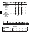
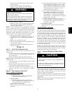
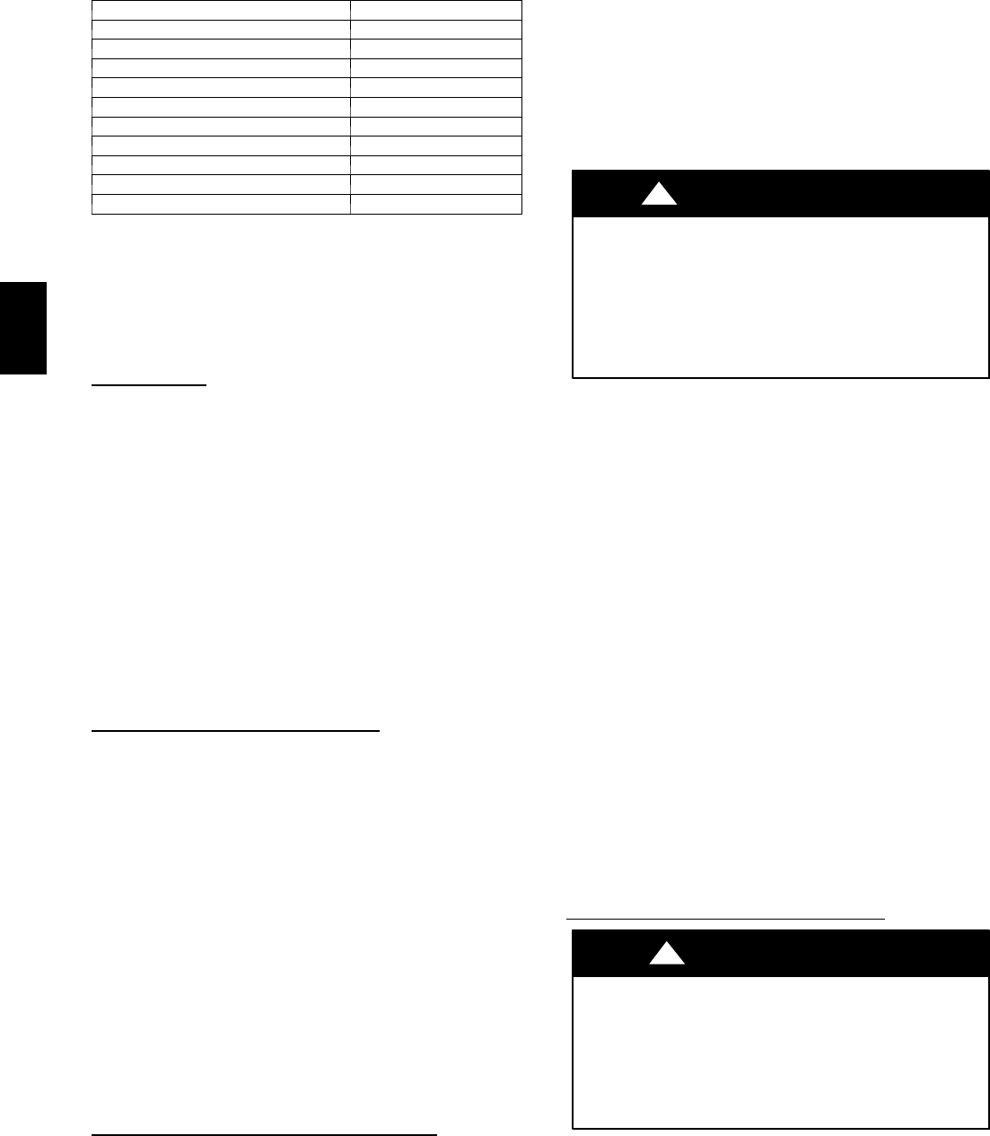
Table 5 – LED Indications
STATUS CODE LED INDICATION
Normal Operation
2
On
No Power Hardware Failure Off
Limit Switch Fault 2 F lashes
Flame Sense Fault 3 F lashes
Four Consecutive Limit Switch Faults 4 F lashes
Ignition Lockout Fault 5 Flashes
Pressure Switch Fault 6 Flashes
Rollout Switch Fault 7 F lashes
Internal Control Fault 8 Flashes
Temporary 1 hr auto reset
1
9 F lashes
NOTES:
1.Th is code indicates an i nternal processor fau lt that will r eset itself in one
hr. Fault can be caused by stray RF signals in the structure or nearby. This
is a UL requirement.
2. LED indicates acceptable operation. Do not change ignition control
board.
3. When W is energized the burners will remain on for a minimum of 60 sec.
4.IfmorethanoneerrormodeexiststheywillbedisplayedontheLEDin
sequence.
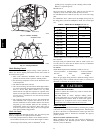
Rollout Switch
The function of th e rollout switch is to close the main gas valve in
the event of flame rollout. The switch is located above the main
bur ners. When the temperatur e at the rollout switch reaches the
maximum allowable temperature, th e con trol circuit trips, clos ing
the gas valve and stopping gas flow to the burners. The indoor
(evaporator) fan motor (IFM) and induced draft motor continue to
run until switch i s r eset. The IGC LED will display FAULT CODE
7.
Step 4 — Start--up Cooling and Make Adjust-
ments
Complete the required procedures given in the Pre--Start--Up
section before starting the unit. Do not jumper any safety devices
when operating the unit. Do not operate the compressor when the
outdoor temperature is below 40°F(4.4°C) (unless accessory
low--ambient kit is installed). Do not rapid--cycle the compressor.
Allow 5 minutes between on cycles to prevent compressor damage.
Checking Cooling Control Operation
Start and check the unit for proper cooling control operation as
follows:
1. Place room thermostat SYSTEM switch in OFF position.
Observe that blower motor starts wh en FAN switch is
placed in ON position and shuts down when FAN switch is
placed in AU T O position.
2. Place SY STEM switch in COOL position and FAN switch
in AUTO position. Set cooling control below room
temperature. Observe that compressor, condenser fan, and
evaporator blower motors start. Observe that cooling cycle
shut s down when con trol setting is satisfied. The evaporator
fan will continue to run for 90 sec.
IMPORTANT: Three--phase, scroll compressors units are
direction oriented. Unit must be checked to ensure proper
compressor 3-- phase power lead orientation. If not corrected within
5 minutes, the internal protector will shut off the compressor. The
3--phase power leads to the unit must be reversed to correct
rotation. When turning backwards, the difference between
compressor suction and discharge pressures will be near zero.
Checking and Adjusting Refrigerant Charge
The refrigerant system is fully charged with PuronR (R --410A)
refrigerant and is tested and factory sealed. Allow system to operate
a minimum of 15 minutes before checking or adjusting charge.
NOTE: Adjustment of the refrigerant charge is not required unless
the unit is suspected of not having the proper PuronR (R--410A)
charge.
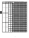
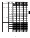
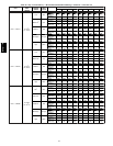
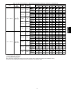
The c harging label and the tables show n refer to system
temperatures and pressures in cooling mode only. A refrigerant
charging label is attached to the inside of the compressor access
panel. The chart includes the required liquid line temperature at
given discharge line pressures and outdoor ambient temperatures.
An accurate therm ocouple-- or thermistor-- type thermometer, and a
gauge manifold are required when using the subcooling charging
method for evaluating the unit charge. Do not use mercury or small
dial--type thermometers because they are no t adequate for this type
of measu rement.
UNIT DAMAGE HAZARD
Failure to follow this caution may result in unit damage.
When evaluating t he refrigerant ch arge, an indicated
adjustment to the specified factory char ge must always be
very minimal. If a substantial adjustment is indicated, an
abnormal condition exists s omewhere in the cooling system,
such as insufficient airflow across either coil or both coils.
!
CAUTION
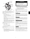
Proceed as follows:
1. Remove caps from low-- and high--p ressure service fittings.
2. Using hoses with valve core depresso rs, attach low-- a nd
high--pressure gauge hoses to low-- and high--pressure
service fittings , r espectively.
3. Start unit in Cooling Mode and let unit run until system
pressures stabilize.
4. Measure and record the following:
a. Outdoor ambient-- air temperature (°F(°C) db).
b. Liquid line temperature (°F(°C).
c. Discharge (high--side) pressure (psig).
d. Suction (low--side) pressure (psig) (for reference only).
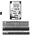
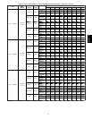
5. Using “Cooling Charging Charts,” compare outdoor--air
temperature(°F(°C) db) with the discharge line pressure
(psig) to determine desired system operating liquid line
temperature (See Fig. 17).
6. Compare actual liquid line temperature with desired liquid
line tem perature. Using a tol erance of ± 2°F(±1.1°C), add
refrigerant if actual tempe rature is more than 2°F(1.1°C)
higher than proper liquid line temperature, or remove
refrigerant if actual temperature is more than 2°F(1.1°C)
lower than required liquid line temperature.
NOTE: If the probl em causing the inaccurate readin gs is a
refrigerant leak, refer to the Check for Refrigerant Leaks section.
Indoor Airflow and Airflow Adjustments
UNIT OPERATION HAZARD
Failure to follow this cautio n may result in unit damage.
For cooling operation, the recommended airflow is 350 to
450 cfm for each 12,000 Btuh of rated cooling capacity. For
heating operation, the airflow must produce a temperature
rise that falls within the range stamped on the un it rating
plate.
CAUTION
!
NOTE: Be sure that all supply--and return --air grilles are open,
free from obstructions, and adjusted properly.
677C-- --A