


3. Restart unit in heating mode, allowing frost to accumulate
on outdoor coil.
4. After a few minutes in heating mode, liquid line tempera-
ture should drop below closing point of defrost thermostat
(approximately 30°F).
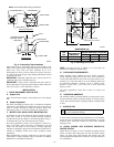
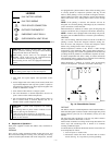
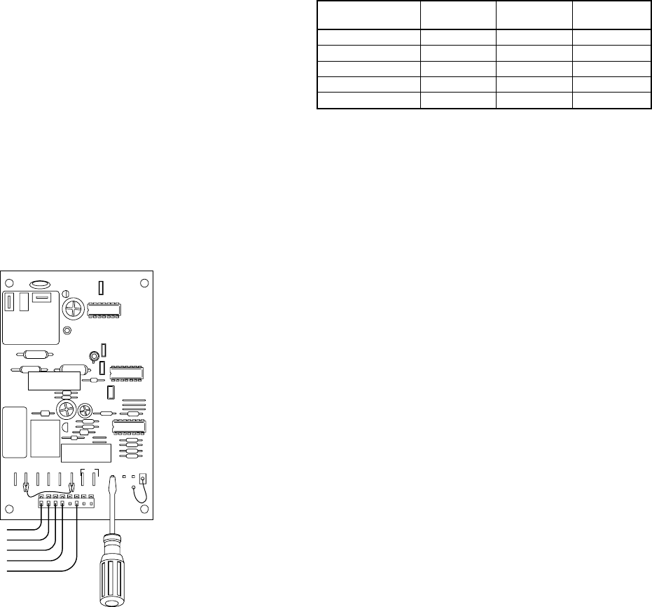
5. Short between speed-up terminals with a flat-bladed screw-
driver. (See Fig. 11.) This reduces the timing sequence to
1/256th of original time. (See Table 2.)
6. When you hear reversing valve change position, remove
screwdriver immediately; otherwise, control will terminate
normal 10-minute defrost cycle in approximately 2 sec.
NOTE: Length of defrost cycle is dependent on the length of time
it takes to remove screwdriver from test pins after reversing valve
has shifted.
7. Unit will remain in defrost for remainder of defrost cycle
time or until defrost thermostat reopens at approximately
80°F coil temperature of liquid line.
8. Turn off power to outdoor unit and reconnect fan motor lead
to OF2 on control board. (See Fig. 11.)
XIV. CHECK CHARGE
Factory charge is shown on unit rating plate. To check charge in
cooling mode, refer to Cooling Only Procedure on unit wiring and
charging label. To check charge in heating mode, refer to Heating
Check Chart Procedure.
NOTE: If superheat or subcooling charging conditions are not
favorable, charge must be weighed in accordance with unit rating
plate ± 0.6 oz/ft of 3/8-in. liquid line above or below 15 ft
respectively.
A. Heating Check Chart Procedure
To check system operation during heating cycle, refer to the
Heating Check Chart on outdoor unit. This chart indicates whether
a correct relationship exists between system operating pressure and
air temperature entering indoor and outdoor units. If pressure and
temperature do not match on chart, system refrigerant charge may
not be correct. Do not use chart to adjust refrigerant charge.
NOTE: When charging is necessary during heating season,
charge must be weighed in accordance with unit rating plate ± 0.6
oz/ft of 3/8-in. liquid line above or below 15 ft respectively.
EXAMPLE:
To calculate additional charge required for a 25-ft line set:
25 ft - 15 ft = 10 ft X 0.6 oz/ft =6 oz of additional charge
XV. FINAL CHECKS
IMPORTANT: Before leaving job, be sure to do the following:
1. Securely fasten all panels and covers.
2. Tighten service valve stem caps to 1/12-turn past finger
tight.
3. Leave User’s Manual with owner. Explain system operation
and periodic maintenance requirements outlined in manual.
4. Fill out Dealer Installation Checklist and place in customer
file.
CARE AND MAINTENANCE
For continuing high performance and to minimize possible equip-
ment failure, periodic maintenance must be performed on this
equipment.
Frequency of maintenance may vary depending upon geographic
areas, such as coastal applications.
Fig. 11—Defrost Control
A91444
OF1
OF2
O
R
T2 Y
TI
DFT
C
TEST
30
50 90
W1
O
R
W2
Y
C
CES0110063,
CES0130024
TABLE 2—DEFROST CONTROL SPEED-UP
TIMING SEQUENCE
PARAMETER
MINIMUM
(MINUTES)
MAXIMUM
(MINUTES)
SPEED-UP
(NOMINAL)
30-minute cycle 27 33 7 sec
50-minute cycle 45 55 12 sec
90-minute cycle 81 99 21 sec
10-minute cycle 9 11 2 sec
5 minutes 4.5 5.5 1 sec
© 2002 Bryant Heating & Cooling Systems 7310 W. Morris St. Indianapolis, IN 46231
—8—
Printed in U.S.A. 661c187 Catalog No. 5366-119