


CAUTION: To prevent personal injury wear safety
glasses, protective clothing, and gloves when handling
refrigerant and observe the following:
•Back-seating service valves are not equipped with
Schrader valves. Fully back seat (counterclockwise)
valve stem before removing gage-port cap.
•Front-seating service valves are equipped with Schrader
valves.
CAUTION: Do not vent refrigerant to atmosphere. Re-
cover during system repair or final unit disposal.
1. Fully back seat (open) liquid- and vapor-tube service
valves.
2. Unit is shipped with valve stem(s) front seated (closed) and
caps installed. Replace stem caps after system is opened to
refrigerant flow. Replace caps finger-tight and tighten with
wrench an additional 1/12 turn.
3. Close electrical disconnects to energize system.
4. Set room thermostat to desired temperature. Be sure set
point is below indoor-ambient temperature.
5. Set room thermostat to HEAT or COOL and fan control to
ON or AUTO mode, as desired. Operate unit for 15
minutes. Check system-refrigerant charge.
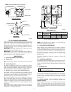
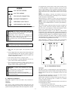
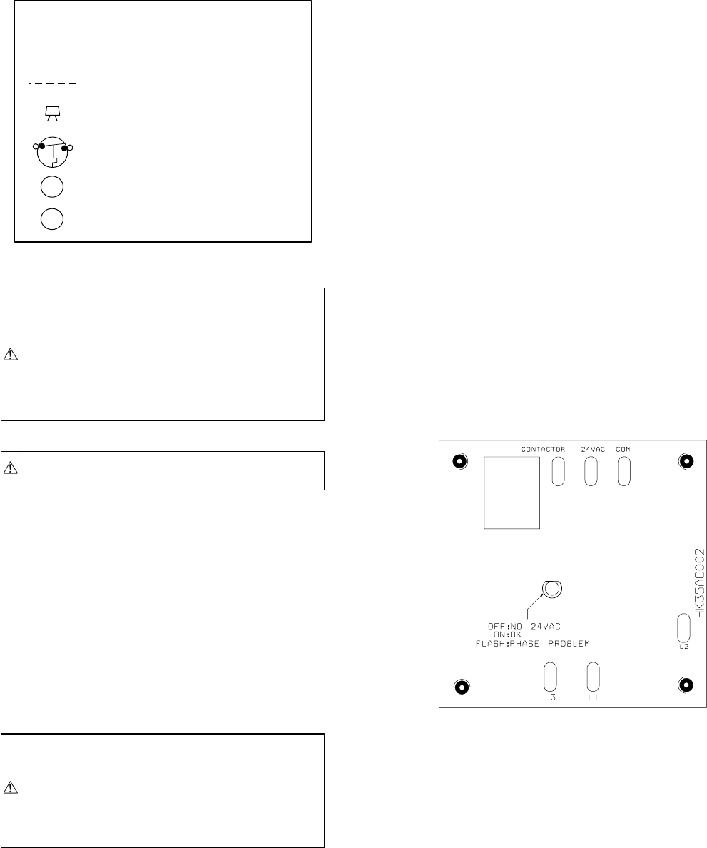
CAUTION: • 3-phase scroll compressors are rotation
sensitive.
• A flashing LED on phase monitor indicates reverse
rotation. (See Fig. 10 and Table 3.)
• This will not allow contactor to be energized.
• Disconnect power to unit and interchange 2 field wiring
leads on unit contactor.
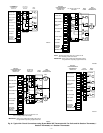
A. Sequence of Operation l .
With power supplied to indoor and outdoor units, transformer is
energized.
COOLING
On a call for cooling, thermostat makes circuits R-O, R-Y, and
R-G. Circuit R-O energizes reversing valve, switching it to cooling
position. On three phase models with scroll compressors, the units
are equipped with a phase monitor to detect if the incoming power
is correctly phased for compressor operation. (See Fig. 10 and
Table 3.) If the phasing is correct, circuit R-Y energizes contactor,
starting outdoor fan motor and compressor circuit. R-G energizes
indoor unit blower relay, starting indoor blower motor on high
speed.
NOTE: If the phasing is incorrect, the contactor will not be
energized. To correct the phasing, interchange any two of the three
power connections on the field side.
When thermostat is satisfied, its contacts open, de-energizing the
contactor and blower relay. Compressor and motors should stop.
NOTE: If indoor unit is equipped with a time-delay relay circuit,
the blower runs an additional 90 sec to increase system efficiency.
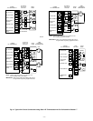
HEATING
On a call for heating, thermostat makes circuits R-Y and R-G. If
phasing is correct, circuit R-Y energizes contactor, starting out-
door fan motor and compressor. Circuit R-G energizes indoor
blower relay, starting blower motor on high speed.
Should temperature continue to fall, R-W2 is made through
second-stage room thermostat bulb. Circuit R-W2 energizes a
sequencer, bringing on first bank of supplemental electric heat and
providing electrical potential to second heater sequencer (if used).
If outdoor temperature falls below setting of outdoor thermostat
(field-installed option), contacts close to complete circuit and bring
on second bank of supplemental electric heat.
When thermostat is satisfied, its contacts open, de-energizing
contactor and sequencer. All heaters and motors should stop.
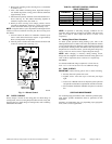
DEFROST
The defrost control is a time/temperature control which includes a
field-selectable (quick-connects located at board edge) time period
between defrost cycles (30, 50, or 90 minutes), factory set at 90
minutes.
The electronic timer and defrost cycle start only when contactor
energized and defrost thermostat is closed.
Defrost mode is identical to cooling mode except that outdoor fan
motor stops and second-stage heat is turned on to continue
warming conditioned space.
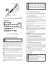
To initiate defrost, the defrost thermostat must be closed. This can
be accomplished as follows:
1. Turn off power to outdoor unit.
2. Disconnect outdoor fan motor lead from OF2 on control
board. (See Fig. 11.) Tape lead to prevent grounding.
A97413
LEGEND
24-V FACTORY WIRING
24-V FIELD WIRING
FIELD SPLICE CONNECTION
OUTDOOR THERMOSTAT
EMERGENCY HEAT RELAY
SUPPLEMENTAL HEAT RELAY
SHR
EHR
ODT
Fig. 10—Phase Monitor Control
A00010
—7—