31
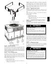
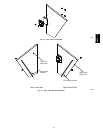
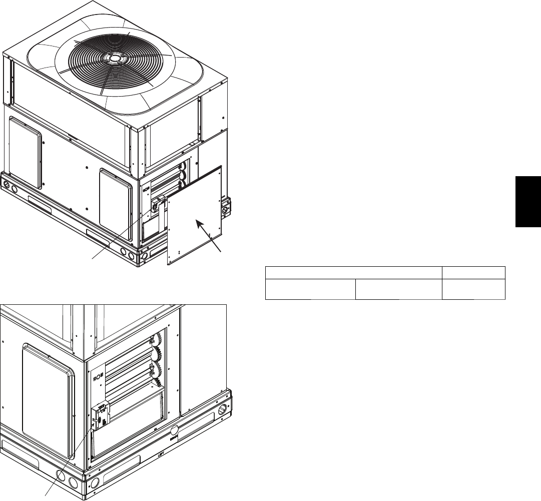
OAT Sensor
Hood Top
Panel
A09689
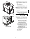
Fig. 23 -- Economizer Hood Top Panel Removal
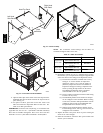
OAT Sensor
A09690
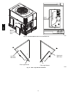
Fig. 24 -- Oat Sensor Installed
6. Replace horizontal return duct cover panel. Screw in place
ensuring all seams are air and watertight.
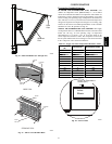
7. Install the 2 angle filter brackets to the right and left hood
side panels respectively with the #10 screws provided. See
Fig. 26.
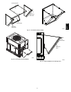
8. Assemble hood according to Fig. 27 screwing together with
provided #10 sheet metal screws.
9. Install assembled hood over the economizer opening in the
replacement retu rn c hamber panel. See Fig. 28. Screw in
place through pre-punched holes. Make sure all seams are
air and watertight.
NOTE: The two wires that connect to the outside air temp erature
sensor (OAT) should remain accessible.
10. Connect the outside air temperature sensor (OAT) to the
economizer per wiring diagram.
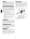
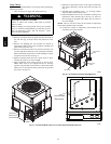
11. O pen the filter clips on the inside of the hood top. Insert the
aluminum filter into the hood and close the clips to hold in
place. See Fig. 29.
12. To replace 12 x 20 x1 (304.8mm x 508mm x 25.4mm) air
filters, open the filter access door (horizontal return duct
cover panel), remove old filters and install new disposable
filters in filter rack. See Table 13 for filter part number.
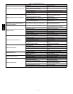
Tabl e 13 – Filter Part Numb er
DESCRIPTION PART NUMBER
Indoor Coil Air Filter
12 x 20 x 1
(304.8 x 508 x 25.4 mm)
KH01AA312
NOTE: The economizer control settings and the filters are
accessible through the filter access door.
13. Economizer controls are set to a standard factory setting.
Nevertheless, you can adjust these settings through the filter
access door. Review the settings in the Operation section:
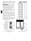
(5.) The standard economizer controller has a factory
setting of “C” for the ou tdoor air temperature
changeover and 63_F(17_C) for the supply air
(mixed air) temperature sensor. The outdoor air
temperature changeover setting is adjus ted on the
sensor by setting the dip switches on the sensor.
The ABCD potentiometer on the economizer
control should be set to the “D” position.
(6.) The low ambient compressor lockout switch setting
is fixed at 42_F(5.6_C).
(7.) T he minimu m position for the outdoor air damper
can be configured at the controller. When not using
aCO
2
sensor, the DCV Max potentiometer must be
completely closed (CCW) f or the Minim um Posi-
tion potentiometer to function c orrectly .
(8.) Settings for the optional outdoor enthalpy sensor,
indoor enthalpy sensor, and CO
2
sensor can also be
configured at the controller.
14. Replace the filter access pan el. Screw in place ensuring all
seams are air a nd watertight.
15. Install all economizer accessories then power H VAC unit
and test cycle economizer.
607C-- --A


