


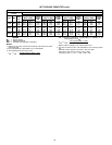
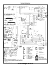
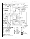
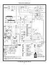
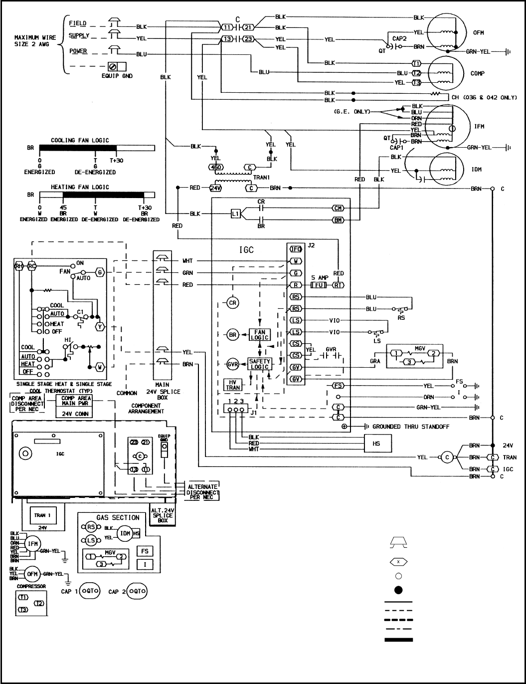
TYPICAL FIELD WIRING (cont)
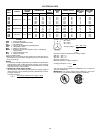
LEGEND
AWG — American Wire Gage
BR — Blower Relay
C—Contactor
CAP — Capacitor
CH — Crankcase Heater
COMP — Compressor Motor
CR — Combustion Relay
EQUIP — Equipment
FL — Fuse Link
FS — Flame Sensor
FU — Fuse
GND — Ground
GVR — Gas Valve Relay
HS — Hall Effect Sensor
HV TRAN — High-Voltage Transformer
I—Ignitor
IDM — Induced-Draft Motor
IFM — Indoor-Fan Motor
IGC — Integrated Gas Control
IP — Internal Protector
LS — Limit Switch
MGV — Main Gas Valve
NEC — National Electrical Code
OFM — Outdoor-Fan Motor
PWR — Power
QT — Quadruple Terminal
RS — Rollout Switch
TRAN — Transformer
Field Splice
Terminal (Marked)
Terminal (Unmarked)
Splice
Factory Wiring
Field Control Wiring
Field Power Wiring
Accessory or Optional Wiring
To Indicate Common Potential
Only, Not to Represent Wiring
NOTES:
1. If any of the original wire furnished must be replaced, it must be re-
placed with type 90 C wire or its equivalent.
2. Thermostat: HH07AT174, HH01AD040, HH01AD046, HH01PC184,
HH01PC185, HH07AT196 Subbase: HH93AZ040, HH93AZ207,
HH93AZ176
3. Use copper conductors only.
Unit 588A Sizes 036-060; 460-3-60
24