


79
11. Shall have a battery back--up capable of a minimum of 10,000 hours of data and time clock retention during power
outages.
12. Shall have built--in support for Bryant technician tool.
13. Shall include an EIA--485 protocol communication port, an access port for connection of either a computer or a
Bryant technician tool, an EIA--485 port for network communication to intelligent space sensors and displays, and
a port to connect an optional LonWorks communications card.
14. Software upgrades will be accomplished by either local or remote download. No software upgrades through chip
replacements are allowed.
23 09 33 Electric and Electronic Control System for HVAC
23 09 33.13 Decentralized, Rooftop Units:
23 09 33.13.A. General:
1. Shall be complete with self--contained low--voltage control circuit protected by a resettable circuit breaker on the
24--v transformer side. Transformer shall have 75VA capability.
2. Shall utilize color--coded wiring.
3. Shall include a central control terminal board to conveniently and safely provide connection points for vital con-
trol functions such as: smoke detectors, phase monitor, gas controller, economizer, thermostat, DDC control op-
tions, and low and high pressure switches.
4. The heat exchanger shall be controlled by an integrated gas controller (IGC) microprocessor. See heat exchanger
section of this specification.
5. Unit shall include a minimum of one 8--pin screw terminal connection board for connection of control wiring.
23 09 33.23.B. Safeties:
1. Compressor over--temperature, over--current. High internal pressure differential.
2. Low pressure switch.
a. Units with 2 compressors shall have different sized connectors for the circuit 1 and circuit 2 low and high pres-
sure switches. They shall physically prevent the cross--wiring of the safety switches between circuits 1 and 2.
b. Low pressure switch shall use different color wire than the high pressure switch. The purpose is to assist the
installer and service technician to correctly wire and or troubleshoot the rooftop unit.
3. High pressure switch.
a. Units with 2 compressors shall have different sized connectors for the circuit 1 and circuit 2 low and high pres-
sure switches. They shall physically prevent the cross--wiring of the safety switches between circuits 1 and 2.
b. High pressure switch shall use different color wire than the low pressure switch. The purpose is to assist the
installer and service technician to correctly wire and or troubleshoot the rooftop unit.
4. Automatic reset, motor thermal overload protector.
5. Heating section shall be provided with the following minimum protections:
a. High temperature limit switches.
b. Induced draft motor speed sensor.
c. Flame rollout switch.
d. Flame proving controls.
23 09 93 Sequence of Operations for HVAC Controls
23 09 93.13 Decentralized, Rooftop Units:
23 09 93.13 INSERT SEQUENCE OF OPERATION
23 40 13 Panel Air Filters
23 40 13.13 Decentralized, Rooftop Units:
23 40 13.13.A. Standard filter section
1. Shall consist of factory installed, low velocity, disposable 2--in. thick fiberglass filters of commercially available
sizes.
2. Unit shall use only one filter size. Multiple sizes are not acceptable.
3. Filters shall be accessible through an access panel with “no--tool” removal as described in the unit cabinet section
of this specification (23 81 19.13.H).
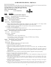
23 81 19 Self--Contained Air Conditioners
23 81 19.13 Small--Capacity Self--Contained Air Conditioners (580J*04--14)
23 81 19.13.A. General
1. Outdoor, rooftop mounted, electrically controlled, heating and cooling unit utilizing a fully hermetic scroll com-
pressor(s) for cooling duty and gas combustion for heating duty.
580J