


174
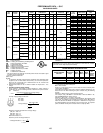
GUIDE SPECIFICATIONS — 581C024-060 (cont)
For the EconoMi$er2, the power exhaust shall be
controlled by the or third party controls.
23. Outdoor Air Enthalpy Sensor (EconoMi$er IV or
EconoMi$er2):
The outdoor air enthalpy sensor shall be used with
the EconoMi$er IV or EconoMi$er2 device to pro-
vide single enthalpy control. When used in conjunc-
tion with a return air enthalpy sensor, the
EconoMi$er IV or EconoMi$er2 device will provide
differential enthalpy control. The sensor allows the
EconoMi$er IV or EconoMi$er2 controller to deter-
mine if outside air is suitable for free cooling.
24. Return Air Enthalpy Sensor (EconoMi$er IV or
EconoMi$er2):
The return air enthalpy sensor shall be used with
the EconoMi$er IV or EconoMi$er2 device. When
used in conjunction with an outdoor air enthalpy
sensor, the EconoMi$er IV or EconoMi$er2 device
will provide differential enthalpy control.
25. Return Air Temperature Sensor (EconoMi$er IV or
EconoMi$er2):
The return air temperature sensor shall be used
with the EconoMi$er IV or EconoMi$er2 device.
When used in conjunction with the standard outdoor
air temperature sensor, the EconoMi$er IV or
EconoMi$er2 device will provide differential temper-
ature control.
26. Indoor Air Quality (CO
2
) Sensor (EconoMi$er2):
a. Shall have the ability to provide demand ventila-
tion indoor air quality (IAQ) control through the
EconoMi$er2 with an IAQ sensor.
b. The IAQ sensor shall be available in duct mount,
wall mount, and wall mount with LED display.
The set point shall have adjustment capability.
c. Requires EconoMi$er2, or Apollo control
options.
27. Indoor Air Quality (CO
2
) Room Sensor (EconoMi$er
IV):
Sensor shall have the ability to provide demand
ventilation control through the EconoMi$er IV. The
IAQ sensor shall be wall mounted with an LED dis-
play in parts per million. The set point shall have
adjustment capability.
28. Return Air CO
2
Sensor (EconoMi$er IV):
Sensor shall have the ability to provide demand
ventilation control through the EconoMi$er IV. The
IAQ sensor shall be duct mounted. The set point
shall have adjustment capability.
29. Gas Heat options (sizes 036-060):
a. Single-stage gas heat shall be provided in lieu of
two-stage heat.
b. NOx reduction shall be provided to reduce
nitrous oxide emissions to meet the California
Air Quality Management NOx requirement of 40
nanograms/joule or less.
c. Primary tubes on low NOx units shall be 409
stainless steel. Other components shall be alu-
minized steel.
30. Ultraviolet Germicidal Lamps:
Ultraviolet germicidal lamps are designed to elimi-
nate odor causing mold and fungus that may
develop in the wet area of the evaporator section of
the unit. The high output, low temperature germi-
cidal lamps are field installed in the evaporator sec-
tion of the unit, aimed at the evaporator coil and
condensate pan. The short wavelength ultraviolet
light inhibits and kills mold, fungus and microbial
growth. The lamps have an output rating at 45F in
400 fpm airflow of 120 microwatts/cm
2
at 1 meter.
31. Perfect Humidity™ Adaptive Dehumidification Sys-
tem:
a. The Perfect Humidity dehumidification system
shall be factory-installed in the rooftop unit, and
shall provide greater dehumidification of the
occupied space by two modes of dehumidifica-
tion operations beside its normal design cooling
mode:
1) Subcooling mode further subcools the hot
liquid refrigerant leaving the condenser coil
when both temperature and humidity in the
space are not satisfied.
2) Hot gas reheat mode shall mix a portion of
the hot gas from the discharge of the com-
pressor with the hot liquid refrigerant leav-
ing the condenser coil to create a two-
phase heat transfer in the system, resulting
in a neutral leaving-air temperature when
only humidity in the space is not satisfied.
b. The system shall consist of a subcooling/ reheat
dehumidification coil located downstream of the
standard evaporator coil. This dehumidification
coil is a two-row coil on the 005 and 006 units,
and a one-row coil on 003 and 004 units.
c. The system shall include crankcase heater(s) for
the scroll compressor(s).
d. The system shall include a low outdoor air tem-
perature switch to lock out both subcooling and
hot gas reheat mode when the outdoor-air tem-
perature is below 40 F.
e. The system shall include a Motormaster® low
ambient control to ensure the normal design
cooling mode capable of down to 0° F low ambi-
ent operation.
f. The system shall include a low-pressure switch
on the suction line to ensure low pressure start-
up of hot gas reheat mode at lower outdoor tem-
perature condition.
g. The system operation may be controlled by a
field-installed, wall-mounted humidistat. The
dehumidification circuit will then operate only
when needed. Field connections for the humidis-
tat are made in the low-voltage compartment of
the unit control box. The sensor can be set for
any level between 55% and 80% relative humid-
ity.
h. The system shall include a Thermal Expansion
Valve (TXV) to ensure a positive superheat con-
dition and a balance of pressure drop.
32. Humidistat:
Field-installed, wall-mounted humidistat is used to
control activation of the dehumidification package.
The humidistat can be set for humidity levels
between 20% and 80% relative humidity.
33. Hinged Panel Option:
Hinged panel option provides hinged access panels
for the filter, compressor, evaporator fan, and con-
trol box areas. Filter hinged panels permit tool-less
entry for changing filters. Each hinged panel is per-
manently attached to the rooftop unit.
581C024-060