10
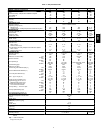
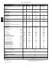
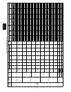
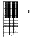
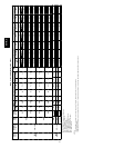
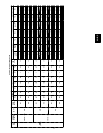
Table 2—Physical Data 551C
BASE UNIT 551C 024 036 048 060
NOMINAL CAPACIT Y (n ominal tons)
2 3 4 5
OPERATING WEIGHT (lb)
Unit
435 445 465 635
Perfect Humidity Adaptive Dehumidification System
13 15 23 25
EconoMi$er IV
50 50 50 50
Roof Cu r b
115 115 115 115
COMPRESSOR
Scroll
Quantity
1 1 1 1
Oil (oz)
25 42 56 53
REFRIGERANT TYPE
R-22
Expansion Device
Acut rol Metering Device
Operating Charge (lb-oz)
Standard Unit
5 --- 3 7 --- 11 8 --- 8 12---11
Unit With Perfect Humidity Adaptive Dehumidification System
10 --- 2 14 --- 0 14---13 21 --- 0
CONDENSER FAN
Propeller
Quantity...Diameter (in.)
1...22 1...22 1...22 1...22
Nominal Cfm
3000 3500 3500 4100
Motor Hp...Rpm
1
/8...825
1
/8...825
1
/8...825
1
/
4
...1100
Watts Input (Total)
180 180 180 320
CONDENSER COIL
3/8--- in. OD Enhanced Copper Tubes, Aluminum Lanced Fins
Rows...Fins/in.
1...17 1...17 2...17 2...17
Total Face Area (sq ft)
14.6 14.6 16.5 16.5
EVAPORATOR COIL
3/8--- in. OD Enhanced Copper Tubes, Aluminum Double-Wavy Fins
Standard Unit
Rows...Fins/in.
2...15 2...15 2...15 4...15
Total Face Area (sq ft)
4.2 5.5 5.5 5.5
Unit with Perfect Humidity Adaptive Dehumid ification System
Rows...Fins/in.
1...17 1...17 2...17 2...17
Total Face Area (sq ft)
3.5 3.9 3.9 3.9
EVAPORATOR FAN
Centrifugal Type, Belt Drive
Quantity...Size (in.)
1...10 x 10 1...10 x 10 1...10 x 10 1...10 x 10
Nominal Cfm
800 1200 1600 2000
Maximum Continuous Bhp Std
0.58
1.20 1.20 1.30/ 2.40*
Hi-Static
2.40 2.40 2.90
Motor Frame Size Std
48
48 48 48/ 56*
Hi-Static
56 56 56
Motor R pm
1620 1620 1620 1725
Fan Rpm Range Std
400-1000
680-1044 770-1185 1035-1460
Hi-Static
1075-1455 1075-1455 1300-1685
Motor Bearing Type
Ball Ball Ball Ba ll
Maximum Fan Rpm
1620 2100 2100 2100
Motor Pulle
y
Pitch Diameter
A
/
B
(
in.
)
Std
2.4/3.2
1.9/2.9 1.9/2.0 2.4/3.4
M
o
t
o
r
P
u
l
l
e
y
P
i
t
c
h
D
i
a
m
e
t
e
r
A
/
B
(
i
n
.
)
Hi-Static
2.8/3.8 2.8/3.8 3.4/4.4
Nominal Motor Shaft Diameter (in.) Std
5
/
8
1/
2
1
/
2
5
/
8
Hi-Static
7
/
8
5
/
8
5
/
8
5
/
8
Fan Pull ey Pitch Diameter (in.) Std
4.0
4.5 4.0 4.0
Hi-Static
4.5
4.5 4.0 4.5
Belt — Type...Length (in.) Std
1...A...36
1...A...36 1...A...36 1....4...40
Hi-Static
1...A...39 1...A...39 1...A...40
Pulley Center Line Distance (in.)
10.0---12.4 10.0-12.4 10.0-12.4 14.7-15.5
S
p
eed Chan
g
e
p
er Full Turn o
f
Std
60
65 70 75
S
p
e
e
d
C
h
a
n
g
e
p
e
r
F
u
l
l
T
u
r
n
o
f
Movable Pulley Flange (rpm)
Hi-Static
65 65 60
Movable Pulle
y
Maximum Full
Std
5
5 5 6
M
o
v
a
b
l
e
P
u
l
l
e
y
M
a
x
i
m
u
m
F
u
l
l
Turns from Closed Position
Hi-Static
6 6 5
Factory Setting — Full Turns Open Std
3
3 3 3
Hi-Static
3
1
/
2
3
1
/
2
3
1
/
2
Factory Speed S etting (rpm) Std
756
826 936 1248
Hi-Static
1233 1233 1396
Fan Shaft Diameter at Pulley (in.)
5
/
8
5
/
8
5
/
8
5
/
8
HIGH-PRESSURE SWITCH (psig)
Standard Compressor Internal Relief
450 50
Cutout
428
Reset (Auto.)
320
LOSS-OF-CHARGE/LOW -PRESSURE
SWITCH (Liquid LIne) (psig)
Cutout
7 3
Reset (Auto.)
22 5
FREEZE PROTECTION THERMOSTAT
Opens (F)
30
Closes (F)
45
OUTDOOR-AIR INLET SCREENS
Cleanable. Screen q uantity and s ize varies with option selected.
RETURN-AIR FILTERS
Throwaway
Quantity...Size (in.)
2...16 x 25 x 2
LEGEN D
Bhp — Brake Horsepower
*Sin gle phase/three phase.
***These units do NOT meet the California low NOx requirements.
†††California SCAQMD compliant low NO
x
modelshave combustionproducts that are
controlled to 40 nanograms per joule or less.
551B,C


