


15
Fan Motors and Drives -- Motor and drive packages are
factory installed in all units. The motor and drive
packages consist of the following items:
1 — fan motor
1 — adjustable motor pulley
1—fanpulley
2 — matched fan belts (524J*25A--30A units)
For instructions on changing fan rotation, changing drive
speeds and adjusting drives, see Pulley and Drive
Adjustment in the Service section.
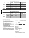
Power Supply and Wiring -- Check the unit data plate to
ensure that available power supply matches electrical
characteristics of the unit. Provide a disconnect switch
with an integrated lock--out feature of size required to
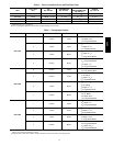
provide adequate fan motor starting current. See Tables
4--6 for unit electrical data.
ELECTRICAL SHOCK HAZARD
Failure to follow this warning could result in personal
injury or death.
Do not use gas piping as an electrical ground. Unit
cabinet must have an uninterrupted, unbroken electrical
ground to minimize the possibility of personal injury if
an electrical fault should occur. This ground may consist
of electrical wire connected to unit ground lug in control
compartment, or conduit approved for electrical ground
when installed in accordance with NEC (National
Electrical Code); ANSI/NFPA 70, latest edition (in
Canada, Canadian Electrical Code CSA [Canadian
Standards Association] C22.1), and local electrical
codes.
!
WARNING
FIRE HAZARD
Failure to follow this warning could result in intermittent
operation or performance satisfaction.
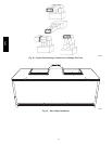
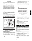
Do not connect aluminum wire between disconnect
switch and fan coil unit. Use only copper wire.
(See Fig. 14)
!
WARNING
COPPER
WIRE ONLY
ELECTRIC
DISCONNECT
SWITCH
ALUMINUM
WIRE
A93033
Fig. 14 -- Disconnect Switch and Unit
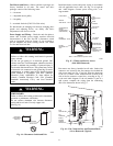
Install disconnect switch and power wiring in accordance
with all applicable local codes. See Fig. 14--16 and the
unit label diagram. Connect power wiring with
1
/
4
-- i n .
ring terminal.
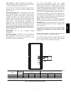
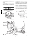
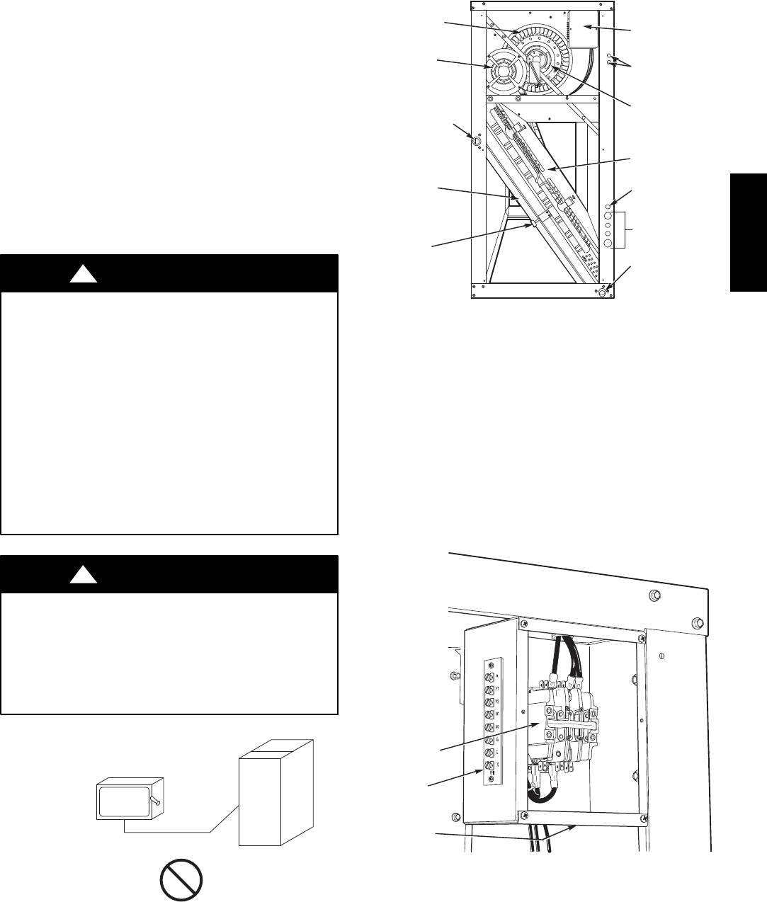
FILTER
ELEMENTS
FILTER
RETAINER
CLIP
FAN SCROLL
CONDENSATE
DRAIN
CONNECTION
(HORIZONTAL)
MOTOR
A
ND DRIVE
FAN
CONTACTOR
BOX
WIRE
ACCESS
COIL
FAN DRIVE
PULLEY
TXV BULB
ACCESS
REFRIGERANT
PIPING ACCESS
CONDENSATE
DRAIN
CONNNECTION
(VERTICAL)
LEGEND
TXV — Thermostatic Expansion Valve
C10693
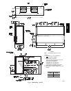
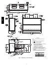
Fig. 15 -- Wiring and Service Access
(Side Panel Removed)
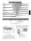
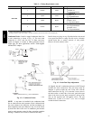
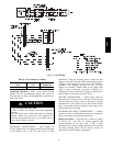
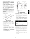
Fan motors are factory--installed on all units. Indoor--fan
contactors are located in the fan contactor box behind the
side access panel (see Fig. 15 and 16). Wire the thermostat
to the 24--v control circuit terminal block located in the
side of the fan contactor control box, according to Fig. 17
or the unit label diagram. If the air handler is part of a
split system, complete the wiring from the condensing
unit to the thermostat shown in Fig. 17.
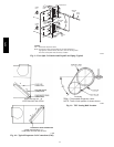
23
22
21
1
3
1
2
1
1
1
0
5
°
C
6
00
VR
J
A
W
FAN
CONTACTOR
24V
TERMINAL
BLOCK
POWER
WIRING
KNOCKOUT
C10694
Fig. 16 -- Fan Contactor Box and Terminal Block
(Cover Removed) (Typical)
524J