


3
12
11
6
8
10
9
7
6
4
5
2
1
13
14
18
3
15
16
17
19
20
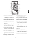
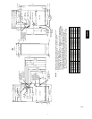
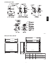
A08421
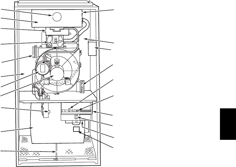
1. Burner sight glass for viewing burner flame.
2. Burner assembly (inside), operates with energy--sav-
ing, inshot burners and hot surface igniter for safe,
dependable heating.
3. Combustion--air intake connection to ensure contam-
inant--free air (right or left side).
4. Redundant gas valve, safe, efficient, features 1 gas
control with 2 internal shutoff valves.
5. Junction box for 115--v electrical power supply.
(right or left side)
6. Vent outlet uses sealed PVC pipe to carry vent gases
from the furnace’s combustion system (right or left
side).
7. Secondary condensing heat exchanger (inside),
wrings out more heat through condensation of gases.
Constructed with polypropylene--laminated steel to
ensure durability.
8. Pressure switch ensures adequate flow of flue
products through furnace and out vent system.
9. Inducer motor pulls hot flue gases through the heat
exchangers, maintaining negative pressure for added
safety.
10. Condensate drain connection collects moisture con-
densed during the combustion process.
123456
11. Heavy--duty blower circulates air across the heat
exchangers to transfer heat into the home.
12. Air filter and retainer may be used for side or bottom
return application.
13. Rollout switch (manual reset) to prevent overtemper-
ature in burner area.
14. Primary serpentine heat exchanger (inside). Stretches
fuel dollars with the S--shaped heat--flow design. Sol-
id weld--free construction of corrosion--resistant alu-
minized steel means reliability.
15. A 3--amp fuse provides electrical and component
protection.
16. Light emitting diode (LED) on control center. Code
lights are for diagnosing furnace operation and ser-
vice requirements.
17. Control center.
18. Blower access panel safety interlock switch.
19. Transformer (24v) behind control center provides
low--voltage power to furnace control center and
thermostat.
20. Power choke (used with 1 HP and 3/4 HP motors.)
353AAV