


—3—
A99001e
CONTROLS—THERMOSTATS AND ZONING
THERMOSTAT—NON-PROGRAMMABLE
For Use with 1-Speed Air Conditioner—TSTATBBNAC01-B
For Use with 2-Speed Air Conditioner—TSTATBBN2S01-B
For Use with 2-Speed Heat Pump—TSTATBBN2S01-B
THERMOSTAT—PROGRAMMABLE
For Use with 1-Speed Air Conditioner—TSTATBBPAC01-B
For Use with 2-Speed Air Conditioner—TSTATBBP2S01-B
For Use with 1-Speed Heat Pump—TSTATBBPDF01-B
For Use with 2-Speed Heat Pump—TSTATBBP2S01-B or TSTATBBPDF01-B
THERMIDISTAT—PROGRAMMABLE THERMOSTAT
—with Humidity Control
TSTATBBPRH01-B
INSTALLATION
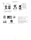
This forced air furnace is equipped for use with natural or propane gas at altitudes 0 - 10,000 ft (0 - 3,050m).
This furnace is for indoor installation in a manufactured (mobile) or modular home.
This furnace may be installed on combustible flooring in alcove or closet at minimum clearance from combustible material.
This appliance requires a special venting system. Refer to the installation instructions for parts list and method of installation. This furnace is for use with schedule-40 PVC,
PVC-DWV, or ABS-DWV pipe, and must not be vented in common with other gas-fired appliances. Construction through which vent/air intake pipes may be installed is
maximum 24 inches (600 mm), minimum 3/4 inches (19 mm) thickness (including roofing materials).
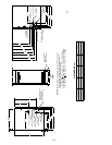
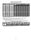
MINIMUM INCHES CLEARANCE TO
COMBUSTIBLE CONSTRUCTION
*
Mimimum front clearance for service 30 inches (762mm).
For installation on combustible floors only when installed on special base No. KGASB0201ALL,
Coil Assembly, Part No. CD5 or CK5, or Coil Casing, Part No. KCAKC.
Clearance in inches
This furnace is approved for
DOWNFLOW installation.
*
BOTTOM
0"
3"
0"
0"
TOP/PLENUM
1"
0"
30
MIN
DOWNFLOW POSITION:
S
I
D
E
F
R
O
N
T
B
C
K
A
S
E
R
V
I
E
C
F
R
O
N
T
S
I
D
E
U
F
R
N
A
C
E
†
†
This furnace must be installed in accordance with the manufacturer's instructions and Manufactured
Home Construction and Safety Standard, Title 24 CFR, Part 3280 or, when such standard is not
applicable, the ANSI A225.1, Standard for Manufactured Home Installation (Manufactured Home Sites,
Communities and Set-Ups), or the Mobile Homes Standard CAN/CSA-Z240 MH Series-M86.
This furnace must be installed with a direct vent (combustion air and flue) system, and use a factory
accessory termination kit.
324997-201 REV. A / LIT
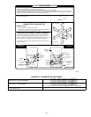
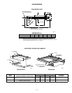
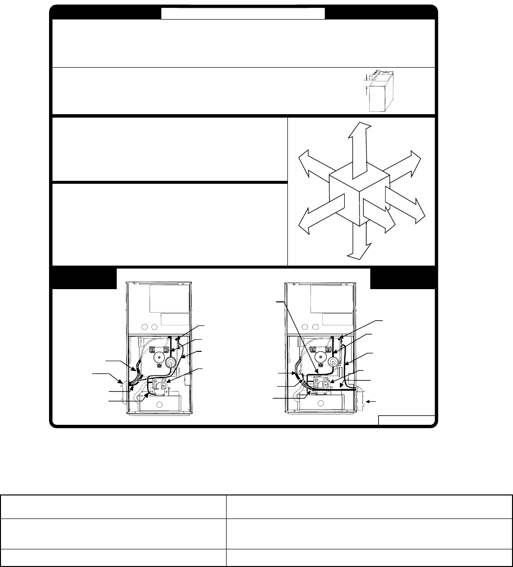
1. All tubing must be connected securely and routed to avoid kinks and traps.
NOTE:
COLLECTOR BOX
DRAIN TUBE
CONDENSATE TRAP
INDUCER HOUSING
DRAIN TUBE
UPPER COLLECTOR BOX
PRESSURE TUBE
COLLECTOR BOX
DRAIN TUBE
DRAIN TUBE
COUPLING
INDUCER HOUSING
DRAIN TUBE
Condensate Trap
on LEFT Side
Condensate Trap
on RIGHT Side
GAS VALVE
CONDENSATE TRAP
COLLECTOR BOX EXTENSION DRAIN
TUBE
LOWER COLLECTOR BOX
PRESSURE TUBE
CAP / PLUG
DRAIN TUBES ROUTED IN
FRONT OF GAS VALVE
UPPER COLLECTOR
BOX PRESSURE TUBE
GAS VALVE
CAP / PLUG
LOWER COLLECTOR
BOX PRESSURE TUBE
BURNER ENCLOSURE
PRESSURE
REFERENCE TUBE
ASSEMBLY
BURNER ENCLOSURE
PRESSURE REFERENCE
TUBE ASSEMBLY
MANUFACTURED MOBILE HOME STANDARDS
TUBE ROUTING
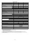
Furnace must be installed level, or pitched forward within 1/2 inch of level for proper drainage. Failure will result
in equipment or property damage.
FRONT
1/2" MAX
TO
LEVEL (0")
DOWNFLOW