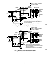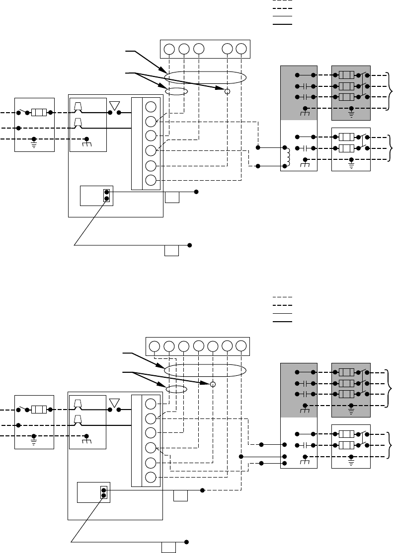
→ Fig. 8—Heating and Cooling Application Wiring Diagram
for 2-Stage Thermostats and/or 2-Speed Condensing Units
A97589
115-V FIELD-
SUPPLIED
FUSED
DISCONNECT
JUNCTION
BOX
CONTROL
BOX
24-V
TERMINAL
BLOCK
FOUR-WIRE
HEATING-
ONLY
SEVEN
WIRE
2-STAGE
THERMOSTAT
TERMINALS
FIELD-SUPPLIED
FUSED DISCONNECT
2-SPEED
CONDENSING
UNIT
FURNACE
G
R
W2 Y2 G Y1
GND
GND
FIELD 24-V WIRING
FIELD 115-, 208/230-, 460-V WIRING
FACTORY 24-V WIRING
FACTORY 115-V WIRING
208/230- OR
460-V
THREE
PHASE
208/230-V
SINGLE
PHASE
Y2
Y1
C
WHT
BLK
WHT
BLK
W1CR
W2
COM
W/W1
Y/Y2
Y1
AFS
NOTE 2
NOTE 1
Connect Y1 and Y/Y2 as shown for proper operation.
Some thermostats require a "C" terminal connection as shown.
If any of the original wire, as supplied, must be replaced, use
same type or equivalent wire.
Connect O to thermostat-O only for heat pump applications.
NOTES: 1.
2.
3.
4.
NOTE 4
O
→ Fig. 7—Heating and Cooling Application Wiring Diagram
for Single-Stage Thermostats and/or Single-Speed Condensing Units
A97588
115-V FIELD-
SUPPLIED
FUSED
DISCONNECT
JUNCTION
BOX
CONTROL
BOX
24-V
TERMINAL
BLOCK
THREE-WIRE
HEATING-
ONLY
FIVE
WIRE
NOTE 2
NOTE 1
1-STAGE
THERMOSTAT
TERMINALS
FIELD-SUPPLIED
FUSED DISCONNECT
CONDENSING
UNIT
FURNACE
NOTE 4
NOTE 5
Y1
AFS
COM
R
WCY RG
GND
GND
FIELD 24-V WIRING
FIELD 115-, 208/230-, 460-V WIRING
FACTORY 24-V WIRING
FACTORY 115-V WIRING
Connect Y/Y2-terminal as shown for proper operation.
Some thermostats require a "C" terminal connection as shown.
If any of the original wire, as supplied, must be replaced, use
same type or equivalent wire.
Y1 is not to be connected.
Connect O to thermostat-O only for heat pump applications.
208/230- OR
460-V
THREE
PHASE
208/230-V
SINGLE
PHASE
WHT
BLK
WHT
BLK
W/W1
W2
Y/Y2
G
NOTES: 1.
2.
3.
4.
5.
O
—6—


