


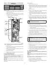


g. Flame-sensing electrode.
h. Wiring connectors leading to control.
12. Reconnect vent pipe to relief box.
13. Replace blower door only.
14. Turn power and gas to ON.
15. Set thermostat and check furnace for proper operation.
16. Verify blower airflow and that airflow rate changes between
heating and cooling.
17. Check for gas leaks.
18. Replace control door.
WARNING: Never use a match or other open flame to
check for gas leaks. Use a soap-and-water solution. A
failure to follow this warning could result in fire, personal
injury, or death.
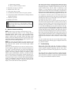
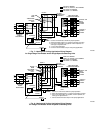
D. Electrical Controls and Wiring
NOTE: There may be more than 1 electrical supply to unit.
The electrical ground and polarity for 115-v wiring must be
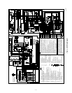
maintained properly. Refer to Fig. 7 and 8 for field wiring
information and to Fig. 9 for unit wiring information. If the
polarity is NOT correct, the furnace control will display rapid
flashing on the status LED and prevent heat operation. The control
system also requires an earth ground for proper operation of the
microprocessor and variable-speed motor.
NOTE: Be aware that measurement of current (amperes) and
power (watts) for the ICM2+ variable-speed motor will be accurate
only when the meter provides true root-mean-square (RMS)
measurements.
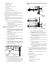
With power disconnected from unit, check all electrical connec-
tions for tightness. Tighten all screws on electrical connections. If
any smoky or burned connections are noticed, disassemble the
connection, clean all parts and stripped wire, and reassemble
properly and securely. Electrical controls are difficult to check
without proper instrumentation; therefore, reconnect electrical
power to unit and observe unit through 1 complete operating cycle.
The 24-v circuit contains an automotive-type, 3-amp fuse located
on the main control. Any 24-v electrical shorts during installation,
service, or maintenance could cause this fuse to blow. If fuse
replacement is required, use ONLY a 3-amp fuse. The control will
display code 24 when the fuse needs replacement.
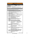
The control in this furnace is equipped with an LED status light to
aid in installation, servicing, and troubleshooting. It can be viewed
through the sight glass or window on the blower access door. The
control indicates status with the LED on continuously, rapid
flashing, or a code composed of 2 digits. (The first digit is the
number of short flashes, the second is the number of longs flashes.)
Refer to the service label on the blower compartment door for code
explanations and useful troubleshooting suggestions. (See Fig. 10.)
It is important to note that power to the furnace must not be
interrupted and the furnace blower door must not be removed until
the LED status code(es) is recorded. When power to the control is
interrupted, the status memory is erased.
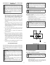
The control will store up to 5 previous codes but will not store
non-current codes longer than 48 hr. To retrieve previous codes, if
present, no thermostat inputs to the control must be present and all
time delays must expire. Remove 1 of the red main limit wires 1
to 4 sec until the LED light goes out, then reconnect it. (See Fig.
4.) (Do not leave red wire disconnected for longer than 4 sec as the
control will assume an overtemperature condition exits and will
respond with indoor blower operation.) This places the control in
the status recall mode and displays the first code stored in memory.
Record the code and repeat the disconnect and reconnect of the red
wire, recording each code until code 11 is displayed indicating no
additional faults. After the last code is displayed or after 2 minutes
in the code recall mode, the control will return to normal standby
mode.
Use any recorded status codes, the service label, and the trouble-
shooting diagram on the following pages to diagnose and correct
any problem condition.
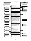
E. Troubleshooting
Refer to the service label. (See Fig. 10.) Page 9 contains a
troubleshooting guide. This guide can be a useful tool in isolating
furnace operation problems. Beginning with the word "Start,"
answer each question and follow the appropriate arrow to the next
item.
The guide will help to identify the problem or failed component.
After replacing any component, verify correct operation sequence.
More information is available in a separate Troubleshooting Guide
for 2-stage gas-fired induced-combustion furnaces.
—5—