


7
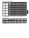
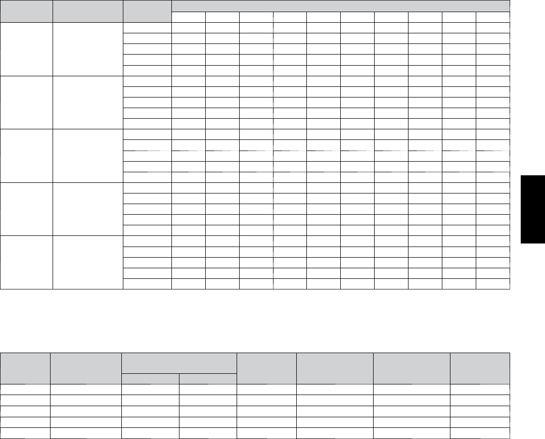
AIR DELIVERY -- CFM (WITH FILTER)*
UNIT SIZE
RETURN---AIR
SUPPLY
SPEED
EXTERNAL STATIC PRESSURE (In. W.C.)
0.1 0.2 0.3 0.4 0.5 0.6 0.7 0.8 0.9 1
024045
Bottom or
Side(s)
5 1185 1145 1115 1075 1035 980 905 820 720 580
4 920 880 835 800 755 720 680 645 605 540
3 735 685 625 585 530 490 435 395 345 295
2 820 765 725 670 630 580 545 490 455 405
1 650 595 535 490 430 390 330 280 235 --- ---
048070
Bottom or
Side(s)
5 1625 1585 1535 1495 1460 1415 1365 1295 1220 1125
4 1405 1360 1320 1280 1240 1195 1155 1115 1070 1030
3 1240 1200 1155 1110 1065 1020 975 935 895 850
2 1190 1140 1095 1050 1000 955 915 870 830 790
1 1035 985 930 885 835 785 745 695 650 600
048090
Bottom or
Side(s)
5 1845 1800 1755 1710 1665 1595 1500 1400 1275 1105
4 1590 1545 1500 1455 1410 1365 1315 1270 1180 1000
3 1365 1320 1270 1215 1170 1125 1070 1025 955 900
2 1225 1160 1110 1060 1010 950 895 830 770 710
1 1100 1030 960 875 805 730 645 570 505 425
060110
Bottom or
Side(s)
5 2255 2205 2150 2100 2040 1985 1920 1835 1735 1615
4 1600 1525 1465 1400 1335 1275 1210 1150 1080 1015
3 1945 1890 1830 1770 1715 1655 1600 1545 1480 1430
2 1420 1340 1280 1200 1140 1065 1005 925 865 790
1 1280 1205 1140 1055 990 910 840 760 695 630
060135
Bottom or
Side(s)
5 2295 2240 2185 2125 2070 2005 1925 1805 1670 1545
4 1725 1660 1605 1545 1460 1395 1340 1285 1230 1170
3 1910 1865 1800 1745 1685 1610 1545 1485 1435 1380
2 1630 1575 1510 1435 1365 1300 1245 1185 1130 1065
1 1430 1355 1285 1200 1125 1075 1015 945 855 800
*A filter is required for each return---air inlet. Airflow performance included 3/4---in. (19 mm) washable filter media such as contained in factory---authorized ac-
cessory filter rack. To determin e airflow performance without this filter, assume an addition al 0.1 In. W.C. available external static pressure.
------ Indicates unstable operating conditions.
ELECTRICAL DATA
UNIT
SIZE
V O LT S ---
H E R T Z ---
PHASE
OPERATING VOLTAGE
RANGE
*
MAXIMUM
UNIT AMPS
MAXIMUM WIRE
LENGTH FT (M)
}
MAXIMUM FUSE
OR CKT BKR
AMPS
{
MINIMUM
WIRE GAGE
Maximum Minimum
024045 1 15 --- 6 0 --- 1 127 104 8.1 34 (10) 15 14
048070 1 15 --- 6 0 --- 1 127 104 9.5 29 (9) 15 14
048090 1 15 --- 6 0 --- 1 127 104 10.3 27 (8) 15 14
060110 1 15 --- 6 0 --- 1 127 104 13.1 34 (10) 20 12
060135 1 15 --- 6 0 --- 1 127 104 13.1 34 (10) 20 12
* Permissible limits of the voltage range at which the unit operates satisfactorily.
{ Time---delay type is r ecommen ded.
}Length shown is as measured 1 way along wire path between unit and service panel for maximum 2 percent voltage drop.
313AAV/JAV