


5
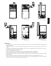
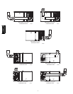
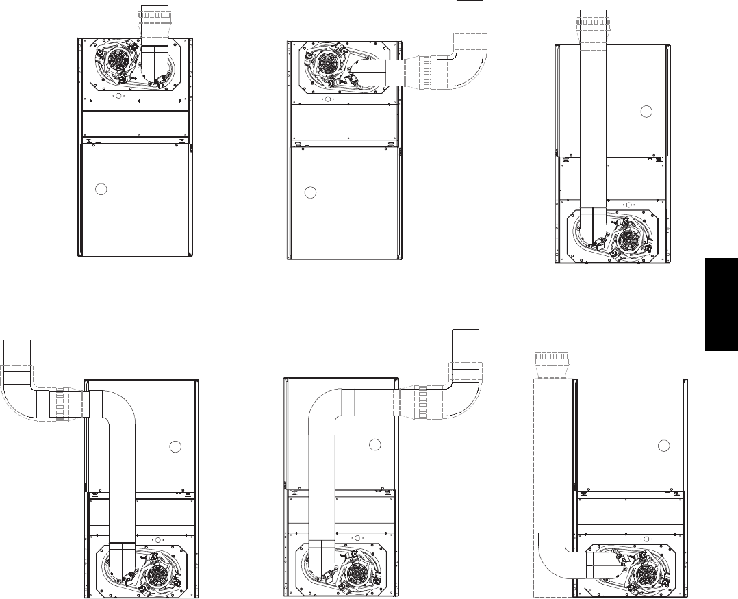
SEE NOTES: 1,2,4,7,8,9
SEE NOTES: 1,2,3,4,7,8,9
SEE NOTES: 1,2,4,5,7,8,9
SEE NOTES:1,2,3,4,5,7,8,9
SEE NOTES: 1,2,3,4,7,8,9
SEE NOTES: 1,2,4,5,6,7,8,9
A02063A02060
A02058
A02059
A02061
A02062
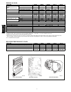
UPFLOW
UPFLOW DOWNFLOW
DOWNFLOW
DOWNFLOW
DOWNFLOW
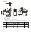
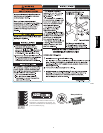
Venting Notes
1. For common vent, vent connector sizing and vent material: United States, latest edition of the National Fuel Gas Code (NFGC),
NFPA54/ANSI Z223.1.
2. Immediately increase to 5--in. (127 mm) vent connector outside furnace casing when 5--in. (127 mm) vent connector required, refer to
Note 1.
3. Side outlet vent for upflow and downflow installations must use Type B vent immediately after exiting the furnace, except when
Downflow Vent Guard is used in downflow position.
4. Type B vent where required, refer to Note 1.
5. 4--in. (102 mm) single wall vent must be used inside furnace casing and the Downflow Vent Guard Kit.
6. Accessory Downflow Vent Guard Kit required in downflow installations with bottom vent configuration.
7. Chimney Adapter Kit required for exterior masonry chimney applications. Refer to Chimney Adapter Kit for sizing and complete
application details.
8. Secure vent connector to furnace elbow with (2) corrosion--resistant sheet metal screws, space approximately 180_ apart.
9. Secure all other single wall vent connector joints with (3) corrosion--resistant screws spaced approximately 120_ apart. Secure Type B
vent connectors per vent connector manufacturer’s recommendations.
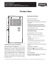
313AAV/JAV