


48
UNIT DAMAGE HAZARD
Failure to follow this caution may result in shortened heat
exchanger life.
Heating fan speed(s) MUST be adjusted to provide proper
air temperature rise as specified on the rating plate.
Recommended operation is at the midpoint of the rise range
or slightly above. Refer to “SET TEMPERATURE RISE”
under START--UP, ADJUSTMENT, and SAFETY
CHECK.
CAUTION
!
14. Reinstall 2 screws securing blower assembly to blower
deck.
15. Refer to furnace wiring diagram, and connect thermostat
leads if previously disconnected.
16. To check blower for proper rotation:
a. Turn on electrical supply.
b. Manually close blower access door switch.
NOTE: If thermostat terminals are jumpered at the time blower
access door switch is closed, blower will run for 90 sec before
beginning a heating or cooling cycle.
c. Perform component self--test as shown at the bottom of
the SERVICE label, located on the front of blower access
door.
d. Verify blower is rotating in the correct direction.
17. If furnace is operating properly, RELEASE BLOWER
ACCESS DOOR SWITCH. Remove any jumpers or re-
connect any disconnected thermostat leads. Replace
blower access door.
ELECTRICAL SHOCK HAZARD
Failure to follow this warning could result in personal
injury, or death.
Blower access door switch opens 115--v power to furnace
control. No component operation can occur unless switch is
closed. Exercise caution to avoid electrical shock from
exposed electrical components when manually closing this
switch for service purposes.
!
WARNING
18. Downflow or horizontal furnaces with vent pipe through
furnace only:
a. Installandconnectshortpieceof ventpipeinsidefurnace
to existing vent.
b. Connect vent connector to vent elbow.
19. Reinstall outer door.
20. Turn on gas supply and cycle furnace through one com-
plete heating and cooling cycle. Verify the furnace temper-
ature rise as shown in Adjustments Section. Adjust tem-
perature rise as shown in Adjustments Section. If outdoor
temperature is below 70_F(21_C) turn off circuit breaker
to outdoor unit before running furnace in the cooling
cycle. Turn outdoor circuit breaker on after completing
cooling cycle.
CLEANING HEAT
EXCHANGER
The following steps should be performed by a qualified
service agency:
NOTE: If the heat exchangers get a heavy accumulation of soot
and carbon, they should be replaced rather than trying to clean
them thoroughly. A build--up of soot and carbon indicates that a
problem exists which needs to be corrected, such as improper
adjustment of manifold pressure, insufficient or poor quality
combustion air, incorrect size or damaged manifold orifice(s),
improper gas, or a restricted heat exchanger. Action must be taken
to correct the problem.
If it becomes necessary to clean the heat exchangers because of
dust or corrosion, proceed as follows:
1. Turn OFF gas and electrical power to furnace.
2. Remove outer access door.
3. Disconnect vent connector from furnace vent elbow.
4. For downflow or horizontal furnace having an internal
vent pipe, remove internal vent pipe within the casing.
5. Disconnect wires to the following components. Mark
wires to aid in reconnection of (be careful when discon-
necting wires from switches because damage may occur):
a. Draft safeguard switch.
b. Inducer motor.
c. Pressure switches.
d. Limit overtemperature switch.
e. Gas valve.
f. Hot surface igniter.
g. Flame--sensing electrode
h. Flame rollout switches.
6. Remove screws that fasten the collector box assembly to
the cell panel. Be careful not to damage the collector box.
Inducer assembly and elbow need not be removed from
collector box.
7. Disconnect gas line from gas manifold.
8. Remove the 5 screws that attach the burner assembly to
the cell panel. The gas valve and individual burners need
not be removed from support assembly. Remove NOx
baffles if installed.
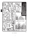
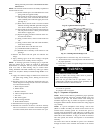
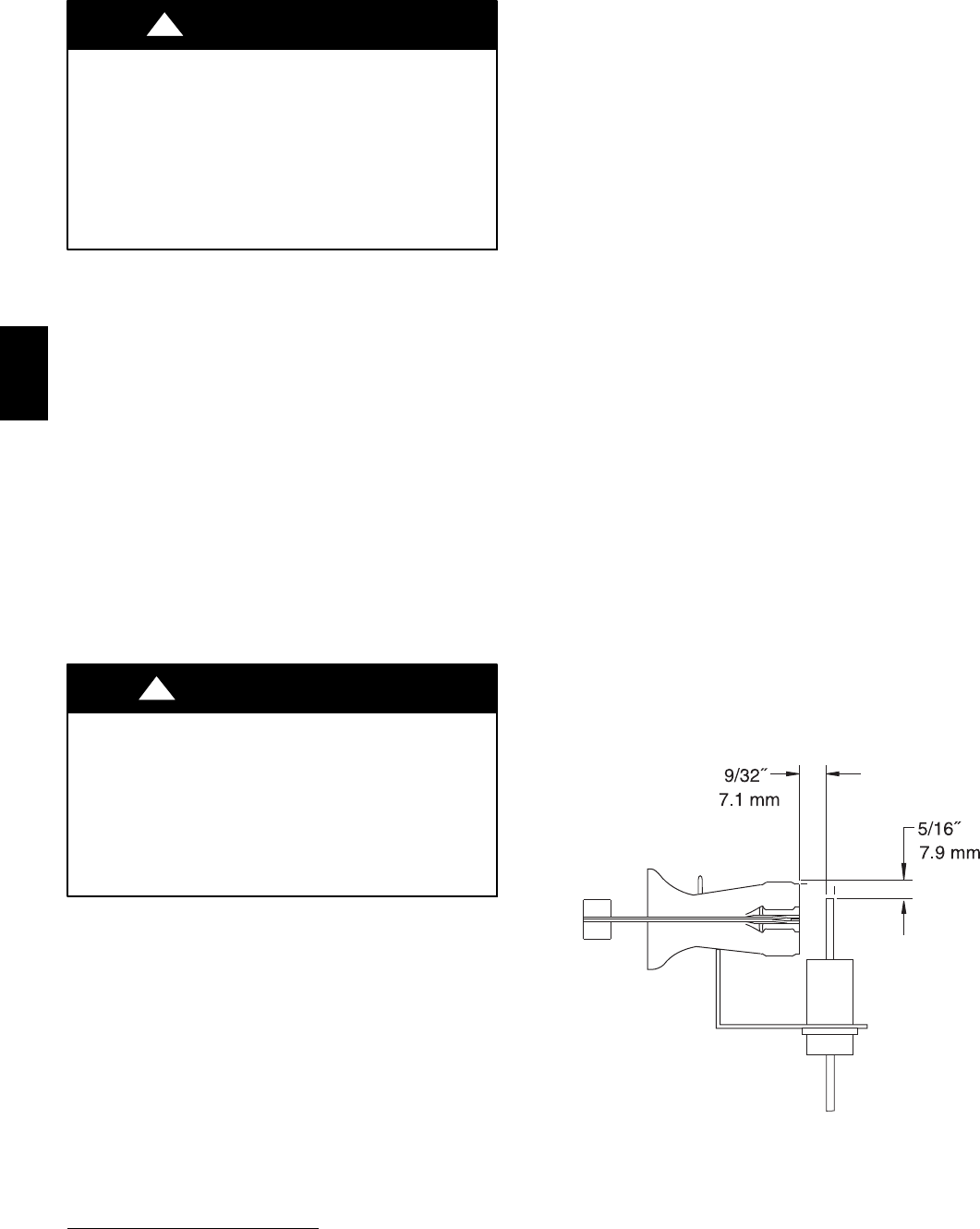
NOTE: Be very careful when removing burner assembly to
avoid breaking igniter. See Fig. 53 and 54 for correct igniter
location.
A05025
Fig. 53 -- Igniter Position--Side View
9. Using field--provided 25--caliber rifle cleaning brush,
36--in. (914 mm) long 1/4--in. (6 mm) diameter steel
spring cable, a variable speed, reversible electric drill, and
vacuum cleaner, clean cells as follows:
a. Remove metal screw fitting from wire brush to allow in-
sertion into cable.
b. Insert the twisted wire end of brush into end of spring
cable, and crimp tight with crimping tool or crimp by
312AAV