


35
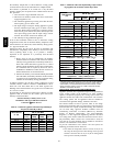
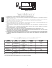
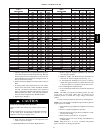
Table 11 – Altitude Derate Multiplier for U.S.A.
ALTITUDE
FT. (M)
PERCENT
OF DERATE
DERATE MULTIPLIER
FACTOR*
0–2000
(0---610)
0 1.00
2001–3000
(610---914)
8–12 0.90
3001–4000
(914---1219)
12–16 0.86
4001–5000
(1219---1524)
16–20 0.82
5001–6000
1524---1829)
20–24 0.78
6001–7000
(1829---2134)
24–28 0.74
7001–8000
(2134---2438)
28–32 0.70
8001–9000
(2438---2743)
32–36 0.66
9001–10,000
(2743---3048)
36–40 0.62
* Derate mu l tiplier factors are based on midpoint altitude for altitude
range.
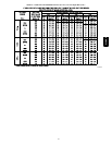
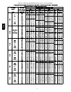
Low NOx models in downflow or horizontal positions MUST
use Table 16 (21,000 BTUH per burner). See input listed on
rating plate.
a. Obtain averageyearly gasheatvalue(at installedaltitude)
from local gas supplier.
b. Obtain average yearly gas specific gravity from local gas
supplier.
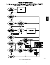
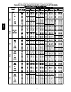
c. Find installation altitude in Table 15 or 16.
d. Find closest natural gas heat value and specific gravity
in Table 15 or 16.
e. Follow heat value and specific gravity lines to point of
intersection to find orifice size and low--and high--heat
manifold pressure settings for proper operation.
f. Check and verify burner orifice size in furnace. NEVER
ASSUME ORIFICE SIZE. ALWAYS CHECK AND
VERIFY.
g. Replace orifice with correct size, if required by Table 15
or 16. Use only factory--supplied orifices. See
EXAMPLE 1.
EXAMPLE 1: (0--2000 ft. / 0--610 M altitude)
For 22,000 Btuh per burner application, use Table 15.
Heating value = 1000 Btuh/cu ft.
Specific gravity = 0.62
Therefore: Orifice No. 43*
Manifold pressure: 3.7--In. W.C. for high--heat
1.6--In. W.C. for low--heat
* Furnace is shipped with No. 43 orifices. In this example
all main burner orifices are the correct size and do not need
to be changed to obtain proper input rate.
3. Adjust manifold pressure to obtain low fire input rate. (See
Fig. 48.)
a. Turn gas valve ON/OFF switch to OFF.
b. Remove manifold pressure tap plug from gas valve.
c. Connect a water column manometer or similar device to
manifold pressure tap.
d. Turn gas valve ON/OFF switch to ON.
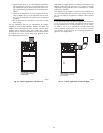
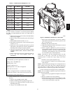
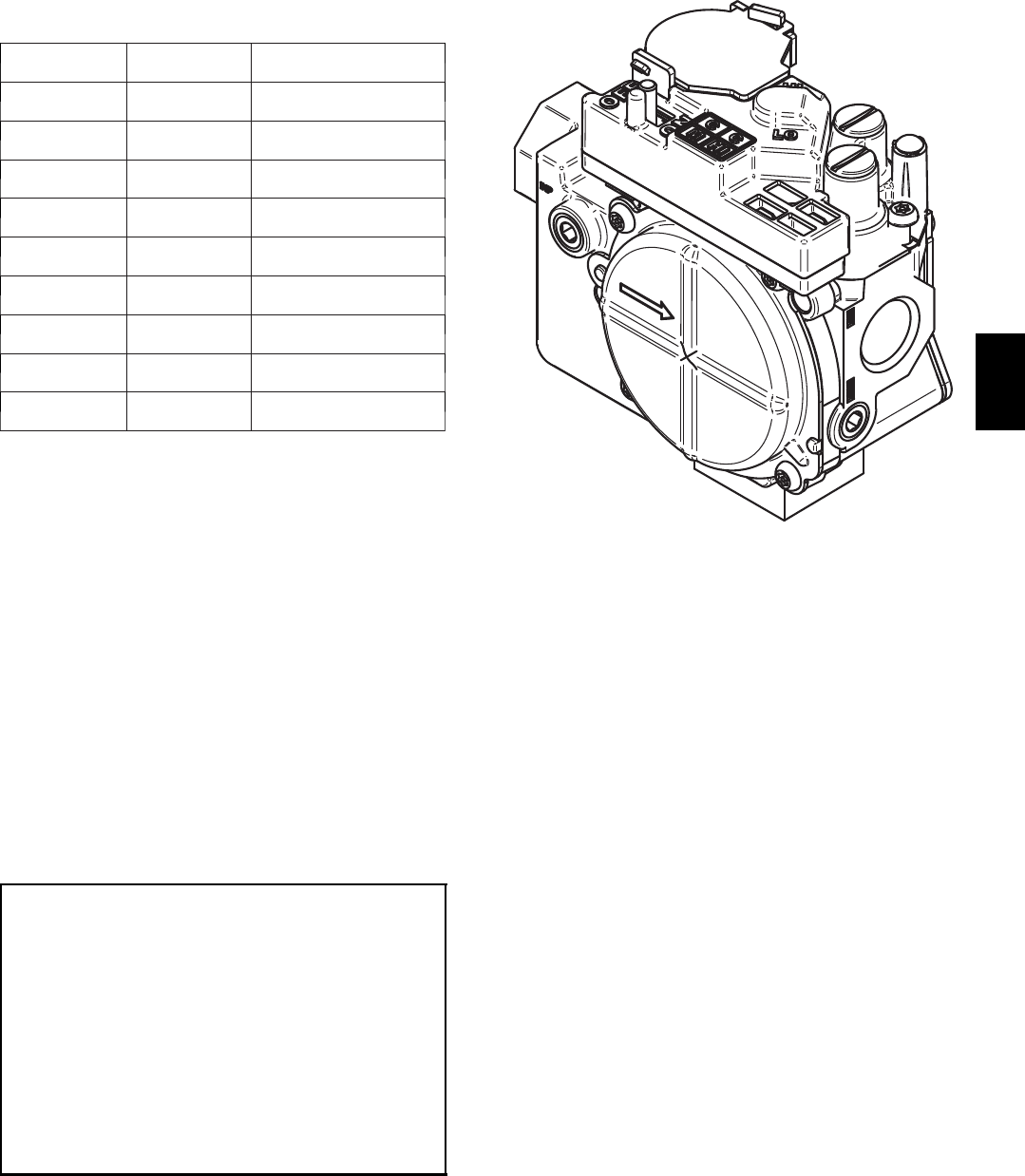
A06667
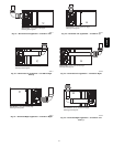
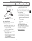
Fig. 48 -- Redundant Automatic Gas Control Valve
e. Move setup switch LHT (SW--1) on furnace control to
ON position to lock furnace in low--heat operation. (See
Fig. 33 and Table 10.)
f. Manually close blower door switch.
g. Jumper R and W/W1 thermostat connections on control
to start furnace. (See Fig. 33.)
h. Remove regulator adjustment cap from low--heat gas
valve pressure regulators. (See Fig. 48.) Turn low--heat
adjusting screw (3/16 in. (5 mm) or smaller flat tipped
screwdriver) counterclockwise (out) to decrease input
rate or clockwise (in) to increase input rate.
NOTE: DO NOT set low--heat manifold pressure less than
1.4--In. W.C. or more than 1.7--In. W.C. for natural gas. If
manifold pressure is outside this range, change main burner
orifices.
i. Install low--heat regulator adjustment cap.
j. Leave manometer or similar device connected and pro-
ceed to Step 4.
NOTE: If orifice hole appears damaged or it is suspected to have
been re--drilled, check orifice hole with a numbered drill bit of
correct size. Never re--drill an orifice. A burr--free and squarely
aligned orifice hole is essential for proper flame characteristics.
4. Verify natural gas low--heat input rate by clocking meter.
NOTE: Gas valve regulator adjustment caps must be in place for
proper input to be clocked.
a. Turn off all other gas appliances and pilots served by the
meter.
b. Run for 3 minutes in low--heat operation.
c. Measure time (in sec) for gas meter to complete 1 revolu-
tion and notereading. The 2 or5 cubicfeetdialprovides
a more accurate measurement of gas flow.
312AAV