


9
Check Charge
All 180A and 187A units must be charged in high stage only.
Factory charge amount and desired subcooling are shown on unit
rating plate. Charging method is shown on information plate inside
unit. To properly check or adjust charge, conditions must be
favorable for subcooling charging. Favorable conditions exist
when the outdoor temperature is between 70_F and 100_F
(21.11_C and 37.78_C), and the indoor temperature is between
70_F and 80_F (21.11_C and 26.67_C). Follow the procedure
below:
Unit is factory charged for 15 ft (4.57 m) of lineset. Adjust charge
by adding or removing 0.6 oz/ft (.018 kg/m) of 3/8 liquid line
above or below 15 ft (4.57 m) respectively.
For standard refrigerant line lengths (80 ft /24.38 m or less), allow
system to operate in cooling mode at least 15 minutes. If conditions
are favorable, check system charge by subcooling method. If any
adjustment is necessary, adjust charge slowly and allow system to
operate for 15 minutes to stabilize before declaring a properly
charged system.
If the indoor temperature is above 80_F (26.67_C), and the
outdoor temperature is in the favorable range, adjust system charge
by weight based on line length and allow the indoor temperature to
drop to 80_F (26.67_C) before attempting to check system charge
by subcooling method as described above.
If the indoor temperature is below 70_F (21.11_C), or the outdoor
temperature is not in the favorable range, adjust charge for line set
length above or below 15ft (4.57 m) only. Charge level should then
be appropriate for the system to achieve rated capacity. The charge
level could then be checked at another time when the both indoor
and outdoor temperatures are in a more favorable range.
NOTE: If line length is beyond 80 ft (24.38 m) or greater than
20 ft (6.10 m) vertical separation, See Long Line Guideline for
special charging requirements.
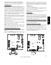
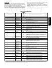
TROUBLESHOOTING
Systems Communication Failure
If communication with the Evolution Control is lost with the user
interface, the control will flash the appropriate fault c ode. (See
Ta ble 6) Check the wiring to the User Interface, indoor and
outdoor units.
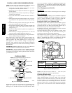
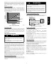
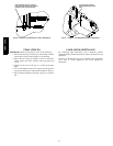
Model Plug
Each control board contains a model plug. The correct model plug
must be installed for or the system to operate properly. (See Table
4.)
The model plug is used to identify the type and size of unit to the
control. On 187A models, the model plug is also used to determine
the start sequence timing for each individual model.
On new units, the model and serial numbers are input into the
board’s memory at the factory. If a model plug is lost or missing at
initial installation, the unit will operate according to the
information input at the factory and the appropriate error code will
flash temporarily. An RCD replacement board contains no model
and serial information. If the factory control board fails, the model
plug must be transferred from the original board to the replacement
board for the unit to operate.
NOTE: The model plug takes priority over factory model
information input at the factory. If the model plug is removed after
initial power up, the unit will operate according to the last valid
model plug installed, and flash the appropriate fault code
temporarily .
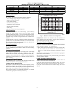
Table 4 – Model Plug Information
MODEL
NUMBER
MODEL PLUG
NUMBER
PIN RESISTANCE
(K---ohms)
Pi ns 1 --- 4 Pins 2---3
187A024 HK70EZ001 5.1 11
187A036 HK70EZ003 5.1 24
187A048 HK70EZ005 5.1 39
187A060 HK70EZ007 5.1 62
180A024 HK70EZ009 5.1 91
180A036 HK70EZ011 5.1 150
180A048 HK70EZ013 5.1 220
180A060 HK70EZ015 5.1 360
Pressure Switch Protection
The outdoor unit is equipped with high-- and low-- pressure
switches. If the control senses the opening of a high or low
pressure switch, it will respond as follows:
1. De-- energize the appropriate compressor contactor,
2. Keep the outdoor fan operating for 15 minutes,
3. Display the appropriate fault code (see Table 6).
4. After a 15 minute delay , if there is still a call for cooling and
the LPS or HPS is reset, the appropriate compressor contac-
tor is energized.
5. If LPS or HPS has not closed after a 15 minute delay, the
outdoor fan is turned off. If the open switch closes anytime
after the 15-- minute delay, then resume operation with a call
for cooling.
6. If LPS or HPS trips 3 consecutive cycles, the unit operation
is locked out for 4 hours.
7. In the event of a high pressure switch trip or high pressure
lockout, check the refrigerant charge outdoor fan operation
and outdoor coil for airflow restrictions.
8. In the event of a low pressure switch trip or low pressure
lockout, check the refrigerant charge and indoor airflow.
Control Fault
If the outdoor unit control board has failed, the control will flash
the appropriate fault code. (See Table 6) The control board should
be replaced.
Brown O ut Protection
If the line voltage is less than 187v for at least 4 seconds, the
appropriate compressor contactor and fan relay are de--energized.
Compressor and fan operation are not allowed until voltage is a
minimum of 190v. The control will flash the appropriate fault
code (see Table 6).
230v Brown-- Out Protection Defeated
The brownout feature can be defeated if needed for severe noisy
power conditions. This defeat should always be a last resort to
solving the problem. Defeat is available on the User Interface
setup screen (available with SYSTXBBUID01-- C UI) or can be
initiated through the forced defrost pins for non--communicating
systems as follows:
The brownout toggle is accomplished by shorting the defrost pins
from power up with the OAT and OCT sensor connector removed.
After 3 seconds, the status of the force defrost short and the
OAT/OCT as open will be checked. If correct, then the brownout
will be toggled.
S Status code 6 shows the brownout is disabled.
S Status code 5 shows the brownout is active.
After the brownout defeat is set, power down and reinstall the
OAT/OCT sensor and remove the short from the forced defrost
pins. As long as the short on the forced defrost remains, the OAT
and OCT faults will not be cleared. The code will continue to be
flashed.
180A / 187A