


3
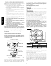
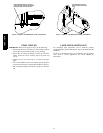
On rooftop applications, locate unit at least 6 in. (152.4 mm) above
roof surface.
Operating Ambient
The minimum outdoor operating ambient in cooling mode is
55_F/12.78_C without low ambient cooling enabled, and the
maximum outdoor operating ambient in cooling mode is
125_F/51.67_C. On Evolution communicating systems only, for
both 180A and 187A models, low ambient cooling is available to
0_F/-- 17.78_C.
Make Piping Connections
PERSONAL INJURY AND ENVIRONMENTAL
HAZARD
Failure to follow this warning could result in personal
injury or death.
Relieve pressure and recover all refrigerant before system
repair or final unit disposal Use all service ports and open
all flow--control devices, including solenoid valves.
!
WARNING
CAUTION
!
UNIT DAMAGE HAZARD
Failure to follow this caution may result in equipment
damage or improper operation.
Do not leave system open to atmosphere any longer than
minimum r equired for installation. POE oil in compressor is
extremely susceptible to moisture absorption. Always keep
ends of tubing sealed during installation.
CAUTION
!
UNIT DAMAGE HAZARD
Failure to follow this caution may result in equipment
damage or improper operation.
If ANY refrigerant tubing is buried, provide a 6 in. (152.4
mm) vertical rise at service valve. Refrigerant tubing lengths
up to 36 in. (914.4 mm) may be buried without further
special consideration. Do not bury lines longer than 36 in.
(914.4 mm).
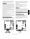
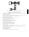
Outdoor units may be connected to indoor section using
field--supplied refrigerant grade tubing of correct size and
condition. For tubing requirements beyond 80 ft (24.38 m),
substantial capacity and performance losses can occur . Following
the recommendations in the Residential Piping and Longline
Guideline will reduce these losses. Refer to Table 1 for field tubing
diameters. Refer to Table 2 for accessory requirements.
There are no buried-- line applications greater than 36 in. (914.4
mm).
If refrigerant tubes or indoor coil are exposed to atmosphere, they
must be evacuated to 500 microns to eliminate contamination and
moisture in the system.
Outdoor Unit Connected to Factory Approved Indoor
Unit:
Outdoor unit contains correct system refrigerant charge for
operation with factory approved ARI rated indoor unit with highest
sales volume when connected by 15 ft (4.57 m) of field--supplied
or factory--accessory tubing, and factory supplied filter drier.
Check refrigerant charge for maximum efficiency.
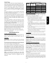
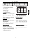
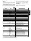
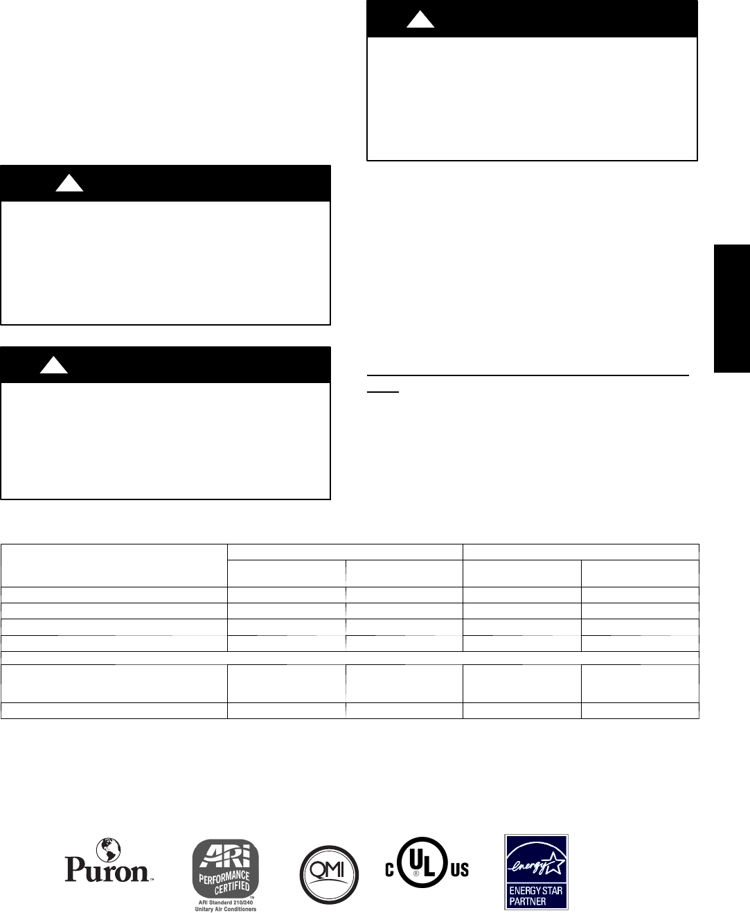
Table 1 – Refrigerant Connections and Recommended Liquid and Vapor Tube Diameters (in.)
UNIT SIZE
LIQUID RATED VAPOR*
Connection
Diameter
Tube
Diameter
Connection
Diameter
Tube
Diameter
187A024 3/8 3/8 5/8 5/8
187A036 3/8 3/8 3/4 3/4
187A048 3/8 3/8 7/8 7/8
187A060 3/8 3/8 7/8 1 --- 1/ 8
180A024
180A036
180A048
3/8 3/8 7/8 7/8
180A060 3/8 3/8 7/8 1 --- 1/ 8
* Units are rated with 25 ft. (7.6 m) of lineset. See Product D ata sheet for performance data when using different size and length linesets.
Notes:
1. Do not apply capillary tube or fixed orifice indoor coils to these units.
2. For Tubing Set lengths between 80 and 200 ft. (24.38 and 60.96 m) horizontal or 20 ft. (6.10 m) vertical differential (250 ft./76.2 m Total Equivalent Length),
refer to the Residential Piping and Longline Guideline.
the environmentally sound refrigerant
REGISTERED
ISO 9001:2000
This product has been designed and manufactured to
meet Energy Star® criteria for energy effici ency when
matched with ap p rop riate coil components. However,
proper refrigerant charge and proper air flow are critical
to achieve rated capacity and efficiency. Installation of
this product should follow all manufacturing refrigerant
chargingand airflow instructions. Failure to confirm
proper charge and airflowmay reduce energy
efficiency and shorten equi pment life.
180A / 187A