


3. INSTALLATION
17
KE-430FX/KE-430FS, BE-438FX
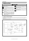
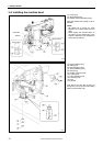
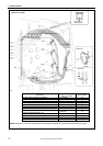
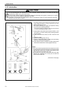
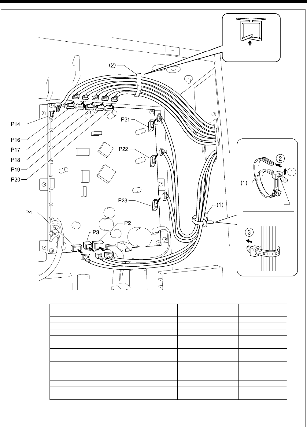
NOTE: Route the X, Y and work clamp pulse motor harnesses so that they do not touch the power supply P.C. board.
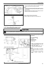
Connectors
Connection location on
main P. C. board
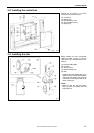
Cord clamps
X pulse motor encoder [5-pin] White P17 (
X
-ENC) (2)
Y pulse motor encoder [5-pin] Blue P18 (
Y
-ENC) (2)
Work clamp pulse motor encoder 5-pin Blac
k
P19 (P-ENC) (2)
Thread nipper pulse motor encoder 5-pin
R
ed P20 (T-ENC) (2)
Machine head switch [3-pin] P14 (HEAD-SW) (2)
Machine head memory [6-pin] P16 (HEAD-M) (2)
Thread trimmer solenoid [6-pin] P2 (SOL1) (1)
Digital tension 4-pin
/Tension release solenoid 4 -pin
P3 (SOL2) (1)
Thread clamp pulse motor [4-pin] Red P4 (TPM) (1)
X
pulse motor [4-pin] White P21 (XPM) (1)
Y
pulse motor [4-pin] Blue P22 (YPM) (1)
Work clamp pulse motor [4-pin] Blac
k
P23 (PPM) (1)
2289B
< Main P. C. board >
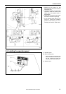
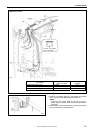
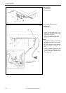
Lock the cord
clamp securely.
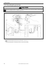
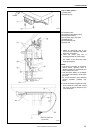
<Removal>
Press
the tab.
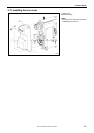
<Securing>