


Page 3
MODEL QTR140L
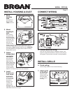
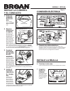
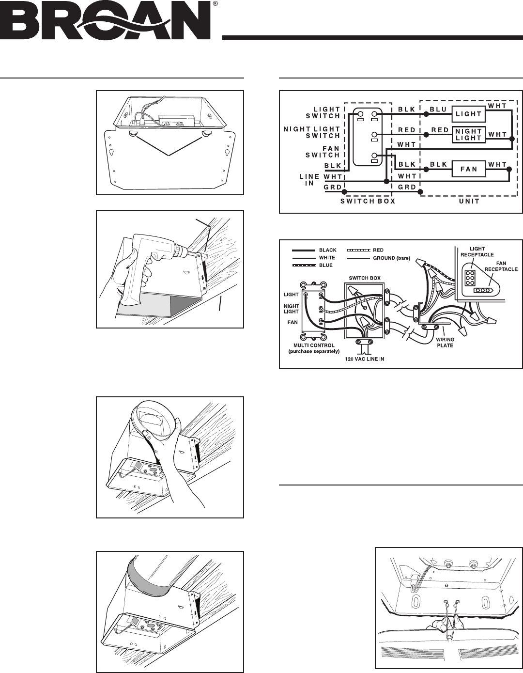
5. Connect electrical wiring.
Run 120 VAC house wiring to installation location. Use
proper UL approved connector to secure house wiring to
wiring plate. Connect wires as shown in wiring diagrams.
CONNECT WIRING
3. Attach
damper/duct
connector.
Snap damper /
duct connector
onto housing.
Make sure con-
nector is ush with
top of housing and
damper ap falls
closed. If using
4-inch ductwork,
install 6” to 4” duct reducer over duct connector.
4. Install
6-inch or 4-
inch round
ductwork.
Connect 6-inch
or 4-inch round
ductwork to
damper / duct
connector or
reducer. Run
ductwork to a
roof cap or wall cap. Tape all ductwork connections to
make them secure and air tight.
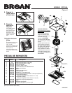
INSTALL HOUSING & DUCT
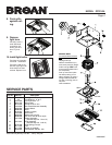
1. Bend
housing
tabs.
Use a pliers to
bend housing
TABS out to 90
0
.
2. Mount
housing to
joist.
Hold housing
in place so that
the housing tabs
contact the bottom
of the joist. The
housing mounts
with four (4)
screws or nails.
SPACER
(use for mounting to I-Joist)
I-JOIST
TABS
INSTALL GRILLE
6. Finish ceiling.
Install ceiling material. Cut out around housing.
7. Attach grille
to housing.
Squeeze grille
springs and insert
them into slots
on each side of
housing.
Screw or nail housing to joist through lowest holes in each
mounting ange, then through highest holes. NOTE:
Mounting to I-JOIST (shown) requires use of SPACERS
(included) between the highest hole of each mounting
ange and the I-joist.