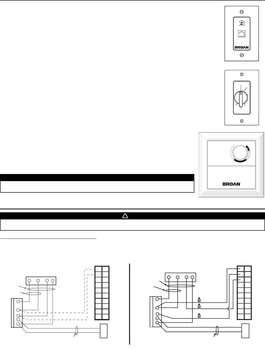
4. CONTROLS (CONT’D)
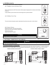
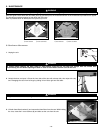
4.4 OPTIONAL AUXILIARY WALL CONTROLS OPERATION
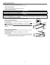
4.4.1 20-MINUTE LIGHTED PUSH-BUTTON TIMER
Set the push-button timer to ON.The fan motors will then operate at high speed for 20 minutes and the indicator
will light up.
To stop activation, push one time; the unit will then get back to previous selection.
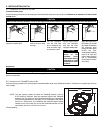
4.4.2 60-MINUTE CRANK
TIMER
This control makes the system operate at high speed for periods varying from 10 to 60 minutes.
VC0084
ON
OFF
10
20
30
40
50
60
TURN
PAST
20
VC0017
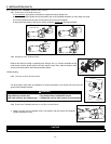
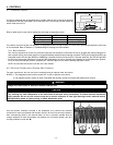
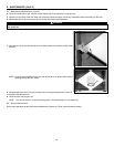
4.4.3 HUMIDITY CONTROL
Setting during the fall, winter and spring months:
Adjust knob to the desired maximum humidity level.
Setting during summer:
Adjust knob to the OFF positon.
CAUTION
Do not select a humidity level below 30%. This could lead to excessive dryness in the air
causing discomfort for the occupants.
C
O
M
F
O
R
T
Z
O
N
E
O
F
F
%
R
E
L
A
T
I
V
E
H
U
M
I
D
I
T
Y
70%
60%
50%
40%
30%
25%
20%
HUMIDITY
CONTROL
VC0085
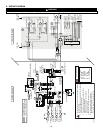
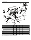
5. ELECTRICAL CONNECTION TO THE FURNACE
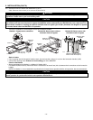
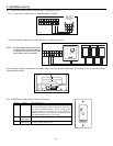
For a furnace connected to a cooling system:
On some older thermostats, energizing the «R» and «G» terminals at the furnace has the effect of energizing «Y» at the thermostat and
thereby turning on the cooling system. If you identify this type of thermostat, you must use the ALTERNATE FURNACE INTERLOCK WIRING.
STANDARD FURNACE INTERLOCK WIRING ALTERNATE FURNACE INTERLOCK WIRING
WARNING
Never connect a 120-volt AC circuit to the terminals of the furnace interlock (standard wiring). Only use the low voltage class
2 circuit of the furnace blower control.
0
!
W R G
Y
W
R
G
C
Y
UNIT TERMINAL CONNECTOR
THERMOSTAT
TERMINALS
FOUR
WIRES
TWO WIRES
heating only
FURNACE
24-VOLT
TERMINAL BLOCK
TWO WIRES
COOLING SYSTEM
NO C NC I OC OL Y R G B
W R G Y
W
R
Y
R
G
Y
C
THERMOSTAT
TERMINAL
4 WIRES
2 WIRES
heating only
wiring
nuts
FURNACE
24-VOLT
TERMINAL BLOCK
2 WIRES
COOLING SYSTEM
NO
NC
C
UNIT TERMINAL CONNECTOR
NO C NC I OC OL Y R G B
VE
0
1
08
A
- 19 -


