


3
This unit has been designed to be as maintenance free as possible, but
ther
e are a few simple things you must do to keep it working properly.
• Test it at least once a week.
• Clean the Strobe Light at least once a month; gently vacuum off
any dust using your household vacuum’s soft brush attachment,
and test the Str
obe Light after cleaning. Never use water, cleaners
or solvents since they may damage the unit.
• If the Strobe Light is loose or broken, the entire unit should be
replaced immediately. Never remove the Strobe Light lens for
any reason. Doing so can permanently damage the unit and
will void your war
ranty
.
• Do no
t paint over the unit. Paint may clog the openings and
pr
event the unit fr
om operating pr
operly
.
REGULAR MAINTENANCE
FOLLOW THESE INSTALLATION STEPS
The basic installation of this str
obe light is similar whether you want
to install one str
obe light or multiple strobe lights.
This device is not a smoke, heat or CO alar
m. It must be intercon-
nected with operating alar
ms to provide protection. It will not
work without AC power.
Things to consider when planning the installation of a hearing impaired
str
obe light:
•
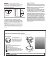
Location of strobe light is important and must comply with NFPA
72 r
equirements. This device is intended to awaken a hearing
impaired person and must be positioned properly for it to be
ef
fective. See Installation Diagram and "Recommended Locations
for Hearing Impair
ed Strobe Lights" for details.
• Types of other alarms to be interconnected with this strobe light.
This device can be interconnected with smoke, heat, carbon
monoxide alarms or a combination of all thr
ee. A smoke alarm is
usually placed within the sleeping room. A carbon monoxide or
heat alarm is usually placed outside the sleeping area. Follow
r
ecommendations in each device's installation manual. The inter-
connect wir
e of all alarms must be properly connected for the
strobe light to be operational. The strobe light may be positioned
anywher
e within the interconnected circuit.
ELECTRICAL SHOCK HAZARD! T
urn off power before starting
installation!
1.
Remove the mounting bracket from the base. Install the mounting
bracket to the junction box.
2.
Using wir
e nuts, connect the power connector to the household
wiring as follows:
Strip of
f about 1/2” (12 mm) of the plastic coating on the orange
wir
e on the power connector.
• Connect the white wire on the power connector to the neutral
wir
e in the junction box.
• Connect the black wire on the power connector to the hot wire
in the junction box.
• Connect the orange wire on the power connector to the inter-
connect wire in the junction box. Repeat for each unit you are
interconnecting. Never connect the hot or neutral wires in the
junction box to the orange interconnect wire.
3. Plug the power connector into the back of the Strobe Light.
4. Line up the alignment tab on the base with the alignment tab on
the mounting bracket. Turn the Strobe Light clockwise (right) until
you hear the unit snap into place.
5. Check all connections.
Improper wiring of the power connector or the wiring leading to
the power connector will cause damage to the Strobe Light and
may lead to a non-functioning unit.
6.
Make sur
e the Strobe Light is receiving AC power. Under normal
operation, the green power indicator light will shine continuously.
If the power indicator light does not light, TURN OFF POWER TO
THE JUNCTION BOX and r
echeck all connections. If all connec
-
tions are correct and the power indicator still does not light when
you restore the power, the unit should be replaced immediately.
7. To test this strobe light you must activate the test button of each
interconnected, smoke, CO or heat alarm. This will send a signal
to the str
obe light and cause the unit to begin flashing.
Depending on what type of alarms you have connected, the
strobe light will flash different patterns.
Smoke/Heat Alarms: Constant approximately 1 flash per second.
CO Alarms: Intermittent appr
oximately 1 flash per second for four
flashes, then 5 seconds off. Pattern is repeated.
These different patterns are to help a hearing impaired person
better distinguish the danger pr
esent. The flash patterns approxi-
mate the audible alarm emitted by either a smoke/heat alarm or
carbon monoxide alarm.
Do not look dir
ectly at or touch the lens while the strobe light is
flashing.
If any Strobe Light does not flash, TURN OFF POWER and recheck
connections. If any Str
obe Light still does not flash when you test it
after r
estoring power, replace it immediately.
•
If you ar
e installing multiple Strobe Lights, repeat steps 1-5
for each Strobe Light in the series. When you are finished,
restore power to the junction box.
This Str
obe Light can be interconnected with all current model hardwired
and ONELINK
®
wir
eless enabled
First Aler
t
®
and BRK Electr
onics
®
branded Smoke Alarms, Carbon Monoxide Alarms, Combination
Smoke/CO Alarms, Heat Alarms and r
elays. Call First Alert Consumer
Affairs at 1-800-323-9005, 7:30 AM - 5:00 PM Central Standard Time,
Monday through Friday for specific model information.
Inter
connect units within a single family residence only, otherwise all
households will experience unwanted alarms when you test any unit
in the series. Interconnected units will only work if they are wired to
compatible units and all r
equirements are met.
Inter
connected units must meet ALL of the following
requirements:
• A maximum of 18 units total may be interconnected
(Maximum of 12 Smoke Alarms).
• The same fuse or circuit breaker must power all interconnected
Alarms.
• The total length of wire interconnecting the units should be
less than 1000 feet (305 meters). This type of wire is commonly
available at Hardware and Electrical Supply stores.
•
All wiring must conform to all local electrical codes and NFPA 70
(National Electrical Code). Refer to NFPA 72, NFPA 101, and/or
your local building code for further connection requirements.
}
}
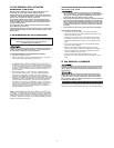
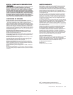
A. Unswitched 120VAC
60 Hz source
B. To additional units (Smoke, CO and
Heat Alarm); Maximum = 18 total
(Maximum 12 Smoke Alarms)
1A. Strobe Light
1B. Smoke, CO or
Heat Alarm
2. Ceiling or Wall
3. Power Connector
4. Wire Nut
5. Junction Box
6. Neutral Wire (Wht)
7. Interconnect Wire
8. Hot Wire (Blk)
ELECTRICAL SHOCK HAZARD! Do not r
estor
e power until
all devices are completely installed. Restoring power before
installation is complete may result in serious electrical shock,
injury or death.