


2
WEEKLY TESTING
T
o test this strobe light you must activate the test button of each inter-
connected, smoke, CO or heat alarm. This will send a signal to the
str
obe light and cause the unit to begin flashing. Depending on what
type of alarms you have connected, the str
obe light will flash different
patterns.
Smoke/Heat Alar
ms:
Constant appr
oximately 1 flash per second.
CO Alarms: Intermittent approximately 1 flash per second for four
flashes, then 5 seconds off. Pattern is repeated.
These dif
ferent patterns are to help a hearing impaired person better
distinguish the danger present. The flash patterns approximate the
audible alarm emitted by either a smoke or heat alarm or a carbon
monoxide alarm. Note that a heat alarm will emit the same hor
n pattern
as a smoke alarm. Make sure all members of your family understand
the dif
ferent flash patterns.
Do not look directly at or touch the lens while the strobe light is
flashing. Doing so can hurt your eyes or burn your fingers.
If the
str
obe light does not flash during testing and the alarm does not sound,
check the fuse or circuit breaker supplying power to the alarm circuit.
If the alarm sounds and the strobe light does not flash, refer to the
installation instructions in this manual to insur
e strobe light is wired
properly. If the strobe light still does not work it should be replaced.
When testing the inter
connected alarm, do not stand too close to
the unit when the alar
m is sounding. It is loud to wake you in an
emergency. Exposure to the horn at close range may harm your
hearing.
All inter
connected alarms connected to this strobe light must
be tested individually to ensur
e proper connections. It is important to
test all interconnected alarms every week to make sure they are working
pr
operly. Using the test button is the recommended way to test the
alarms and str
obe light.
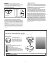
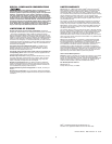
STROBE LIGHT OUTPUT FOR WALL & CEILING
MOUNTING
The intensity of the str
obe light gradually lessens as the angle increases.
In other words, the light is brightest directly in front of the strobe light
and is progressively less bright to either side. As required by
Underwriters Laboratories Inc. (UL), the following illustrations show how
the strobe light is dispersed. Use them to help you choose where to
locate units for the hearing impaired.
PHOTOSENSITIVE EPILEPSY AND STROBE FLASH RA
TES
Individuals who ar
e susceptible to photosensitive epilepsy might have
an increased probability for seizures with multiple strobe lights flashing
asynchr
onously. The frequency or speed of flashing light that is most
likely to cause seizur
es varies from person to person. Generally, flashing
lights most likely to trigger seizures are between the frequency of 5 to
30 flashes per second (Hertz). This str
obe light flashes at about 1 flash
per second.
Under the Americans with Disabilities Act, most workplaces and places
serving the public, including theaters, restaurants, and recr
eation areas,
are required to have fire alarms, which flash as well as ring so that
people who cannot hear or cannot hear well will know that there is an
emer
gency.
90 90
Angle
(In Degrees)
Per
cent
Light Intensity
0
5-25
30-45
50
55
60
65
70
75
80
85
90
100
90
75
55
45
40
35
35
30
30
25
25
45 45
0
90
90
45
45
0
WALL
LIGHT
LIGHT
CEILING
FIGURE 1: Light Output
for
Ceiling Mount
FIGURE 2: Light Output
for Wall Mount
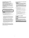
HOW TO INSTALL THIS STROBE LIGHT
THE PARTS OF THIS STROBE LIGHT
1 Mounting slot and screw (1 of 2)
2 Junction box
3 Mounting bracket
4
Mounting Bracket Alignment Arrow
5 Mounting slot and screw (1 of 2)
6 Wire strip gauge
7 Neutral (white) AC wire
8
Hot (black) AC wir
e
9 Interconnect wire
10 Alignment Tab On Alarm
11 Turn to attach to bracket
12 Turn to remove from bracket
The Mounting Bracket
Installs onto the junction box.
It has a variety of screw slots to fit most
boxes. If a junction box is not already in
place, install one using standard #12 or
#14 gauge copper wire.
To remove the mounting bracket from
the base, hold the base firmly and twist
mounting bracket counterclockwise.
The Power Connector
The power connector plugs into a power input block
on the Strobe Light and supplies it AC power.
•Black wir
e is “hot.”
•White wire is neutral.
•Orange wire is used for interconnect.
If you need to remove the power connector, turn
POWER OFF first.
To remove the power connector, insert
a flat scr
ewdriver blade between the power connector and
the security tab inside the power input block. Gently pry
back the tab and pull the connector free.
This Strobe Light is designed to be mounted on any standard wiring junction box to a 4-inch (10 cm) diagonal size, on either the ceiling or wall (if allowed
by local codes). Read “Recommended Placement for Hearing Impaired Strobe Lights” before you begin installation.
Tools you will need: • Standard Flathead screwdriver • Wire strippers
Make sur
e the Alarm is not receiving excessively noisy power. Examples of noisy power could be major appliances on the
same circuit, power from a generator or solar power, light dimmer on the same circuit or mounted near fluorescent lighting. Excessively noisy
power may cause damage to your Alarm.