


M08-0147-000 O 04/05
P
rinted in Mexico
All Rights Reserved. © 2005 BRK Brands, Inc.
B
RK Brands, Inc., 3901Liberty Street Road,Aurora, IL 60504-8122
Consu
mer Affairs: (800) 323-9005 • www.firstalert.com
1
F
ir
s
t
Ale
r
t
®
is a r
e
g
is
t
e
r
e
d t
rademark of the First Alert Trust.
M
ODEL SCO500
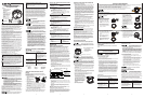
IF YOU ARE CHANGING THE BATTERIES
Action:
1. Insert batteries (2,AA batteries).
Alarm Will Say:
“Welcome, First Alert Carbon Monoxide
and Smoke Alarm. Location [If location
already programmed, example “Kitchen”]
programmed.To select location, press
and hold test button now.”
2
.
P
ress & Hold Test Button if you would
like to change the location.
“
T
o cha
nge location, press and hold test
button after location is heard.” Alarm will
speak list of locations (see below).
3
.
Af
t
e
r y
ou hear t
he location of where
y
ou are placing the Alarm, Press &
Hold the Test Button.
“[L
oca
t
ion
,
e
x
ample “Kitchen”]
l
ocation saved.”
If no location is chosen: “No location
saved.”
Your Alarm has now been programmed for the location of your choice.
A
v
a
i
la
b
le l
ocations:
Base
ment Kitchen Child’s Bedroom
Living Room Dining Room Master Bedroom
Family Room No Location Guest Bedroom
O
f
fice
H
a
llway Utility Room
USING THE SILENCE FEATURES
N
e
v
er rem
o
v
e the batteries to quiet an unwanted alarm. Removing the batteries
disables the alarm and removes your protection.
T
he
Al
arm Si
lence Feature
ca
n t
emporarily quiet an unwanted alarm for several
minutes. You can silence the Smoke/CO Alarm by pressing the Test/Silence button
on the alarm cover for at least 6 seconds.
After the Test/Silence button is released, the Alarm Voice will say “Horn silenced,
detector active.”
The
Low Battery Warning Silence Feature can temporarily quiet the low battery
warning “chirp” for up to 8 hours.You can silence the low battery warning “chirp” by
pressing the Test/Silence button on the alarm cover for at least 3-5 seconds.
Once the low battery warning “chirp” silence feature is activated, the unit continues to
flash the Green light twice a minute for 8 hours.After 8 hours, the low battery “chirp”
will resume.
Replace the batteries as soon as possible; this unit will not operate
without battery power!
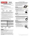
TO LOCK THE BATTERY COMPARTMENT
D
o not lock the battery compartment until you install the batteries and test the
Sm
oke/CO Alarm.
1. Install the batteries before attaching the Alarm to the
bracket. Insert the two (2) AA batteries (included) into the
b
attery compartment. Match the terminals on the end of
the battery with the terminals on the unit. Match “+” to “+”
and “-” to “-.”
I
f t
he batteries are not fully inserted, the unit cannot receive
battery power.
2. Push and hold test button until the alarm sounds.
If the unit does n
ot alarm during testing, DO NOT lock the battery compartment!
Install new batteries and test again. If the unit still does not alarm, replace it
i
mmediately.
3
. Using needle-nose pliers, detach one locking pin from the mounting bracket.
4. Push the locking pin through the hole near the battery door latch on the back of
t
he Smoke/CO Alarm.
OPTIONAL LOCKING FEATURES
TO LOCK THE MOUNTING BRACKET
1. Using needle-nose pliers, detach one locking pin from the mounting bracket.
2
.
I
nsert the locking pin through the hole on the back of the Smoke/CO Alarm as
shown in the diagram.
3. When you attach the Smoke/CO Alarm to the mounting bracket, the locking pin’s
head will fit into a notch on the bracket.
T
he optional locking features are designed to discourage unauthorized removal
of the batteries or alarm. It is not necessary to activate the locks in single-family
h
ouseholds where unauthorized battery or alarm removal is not a concern.
T
his Smoke/CO Alarm has two separate locking features: one to lock the battery
compartment, and the other to lock the Smoke/CO Alarm to the mounting bracket.
Y
ou can choose to use either feature independently, or use them both.
T
ools you will need: • Needle-nose pliers • Standard flathead screwdriver.
Both locking features use locking pins, which are
mo
lded into the mounting bracket. Depending on
w
hich locking features you use, remove one or
both pins from the mounting bracket using needle-
nose p
liers.
T
o permanently remove either locking pin, insert
a fl
athead screwdriver between the locking pin
and the lock, and pry the pin out of the lock.
TO UNLOCK THE BATTERY COMPARTMENT
1. Remove the Smoke/CO Alarm from the mounting bracket. If the unit is locked to
the bracket, see the section “To Unlock the Mounting Bracket.”
2. Insert a flathead screwdriver under the head of the locking pin,
and gently pry it out of the battery compartment lock. (If you
plan to re-lock the battery compartment, save the locking pin.)
3. To relock the battery compartment, close the battery door and
reinsert locking pin in lock.
4. Reattach the Smoke/CO Alarm to the mounting bracket.
When replacing the batteries, always test the Smoke/CO Alarm before relocking
the battery compartment.
TO UNLOCK THE MOUNTING BRACKET
1. Insert a flathead screwdriver into the rectangular cut-out
on the mounting bracket nearest to the locking pin.
2. Pry the Smoke/CO Alarm away from the bracket by
pushing up on the screwdriver and turning the Smoke/
CO Alarm counterclockwise (left) at the same time.
2
QUICK INSTALLATION INSTRUCTIONS
1
. Insert two (2) AA batteries into the battery drawer of the
fi
rst
Alarm a
nd close the
drawer.
2
. The Alarm will sound with a chirp.
3
. You will now be prompted to set the Alarm's location. Follow the direction given
by the Alarm.
Available locations:
Base
ment Kitchen Child’s Bedroom
Living Room Dining Room Master Bedroom
Family Room No Location Guest Bedroom
O
ffice Hallway Utility Room
Y
our Alarm has now been programmed for the location of your choice.
N
OTE: Steps 4 through 6 need to be completed within two minutes. If more
than two minutes pass, the Green power LED will stop blinking. Simply open
the b
attery drawer of the second Alarm and repeat steps 4 through 6.
4
. Insert the batteries into the battery drawer of the
ne
xt
Alarm
. DO NOT CLOSE
THE DRAWER.
5
. Press and hold the test button and then close the battery drawer.
6. Once you hear the unit chirp, release the test button.The Green power LED will
start to blink indicating the ONELINK
TM
Alarm is waiting for program data from
one of the other setup ONELINK
T
M
Alarms.
7. Press and hold the test button on the first Alarm, until the second Alarm chirps
and its Green power LED stops blinking.Then release the test button.
8. If you purchased the Talking Smoke and Carbon Monoxide Alarm, you will now be
prompted to set the Alarm's location. Follow the directions given by the Alarm.
9. If you have purchased the hardwired battery back-up ONELINK
T
M
Alarm, you can
now connect the hardwired Alarm by installing the three-wire connector on the
ceiling to the Alarm.
10. Repeat steps 4-9 for additional ONELINK
T
M
Alarms.
You have now successfully linked your new ONELINK
TM
Alarms.
To add additional Alarms at a later time, follow steps 4 through 9.
QU
ICK AND EASY GUIDE TO PROGRAMMING
YOUR
ONELINK
TM
ALARM AND
US
ING THE OPTIONAL FEATURES
A
ll Alarms Respond as One