


Page 40
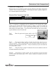
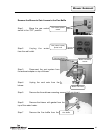
Gas Control Assembly to the Thermal Well (cont’d)
Step 8. To resume operation, follow the instructions located on the water heater
lighting instruction label. Or, use the lighting instructions located in the water heater
installation and operating manual.
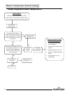
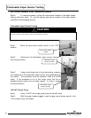
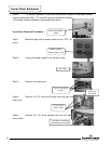
Flammable Vapor Sensor Testing
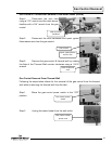
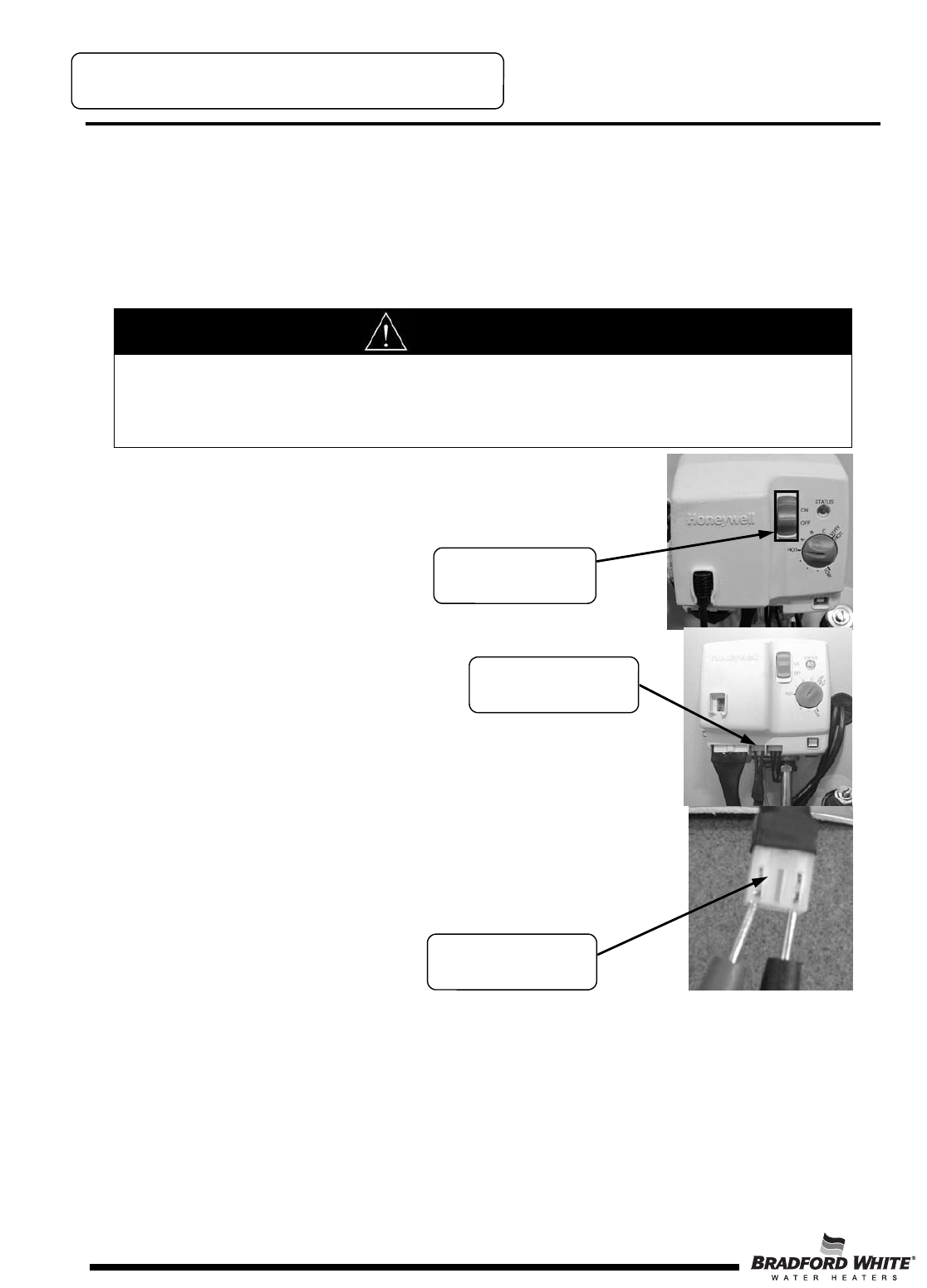
Step 1. Move the gas control power switch to the “OFF”
position.
Step 2. Disconnect the flammable vapor sensor harness
from the gas control.
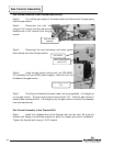
Step 3. Using a multi-meter set to the ohms setting, measure
the resistance of the flammable vapor sensor and resettable ther-
mal switch. The resistance must be between 3,000 and 48,000
ohms. If the resistance is out of this range, verify that the re-
settable thermal switch has not been tripped. If it hasn’t, replace
the thermal switch.
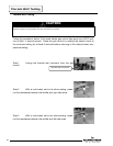
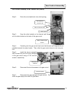
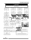
115 VAC Circuit Trace
Step 1. Verify 115VAC and proper polarity are at the wall outlet.
Step 2. With the water heater plugged in and the gas control power switch in the
“ON” position verify LED status.
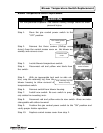
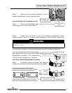
Flammable Vapor Sensor Testing
CAUTION
Do not use standard multi-meter probes for this testing. Doing so will damage the connector. Use special pin type
electronic probes or small diameter wire pins inserted into connector.
Gas control power
switch
Flammable vapor
sensor harness
Flammable vapor
sensor harness
40