


Page 31
Blower Installation (cont’d)
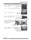
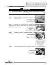
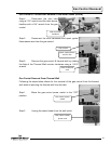
Step 11. Secure blower in place using mounting screws from step 7.
Step 12. Reinstall exhaust adapter from step 4.
Step 13. Reinstall dilution air clip from step 5.
Step 14. Reconnect vent system to exhaust adapter.
Step 15. Reconnect cords from step 6.
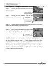
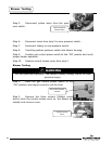
Step 16. Position gas control power switch to the “ON” position.
Step 17. Verify proper blower operation.
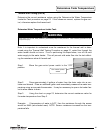
Blower Temperature Switch Testing
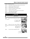
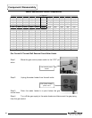
Step 1. Move the gas control power switch to the
“OFF” position.
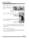
Step 2. Remove the three screws (Phillips screw
driver) from control access cover on blower and remove
cover.
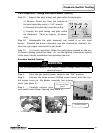
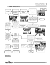
Step 3. Locate the blower temperature switch.
Gas control power
switch
Control access
cover
Blower temperature
switch location
Air mixing
inlet
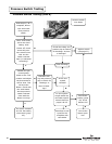
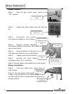
WARNING
115 volt potential exposure. Use caution making voltage checks to avoid
personal injury.
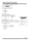
Blower Temperature Switch Testing
31