


Page 28
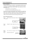
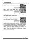
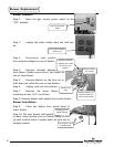
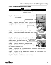
Step 5. Disconnect yellow wires from the pres-
sure switch.
Step 6. Reconnect wires from step 5 to new pressure switch.
Step 7. Reconnect tubing to new pressure switch.
Step 8. Carefully position pressure switch into blower housing.
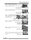
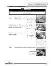
Step 9. Position gas control power switch to the “ON” postion and verify
proper heater operation.
Step 10. Replace control access cover form step 2.
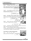
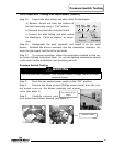
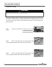
Blower Testing
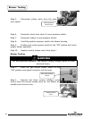
Step 1. Move the gas control power switch to the
“ON” position and adjust control to call for heat.
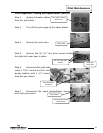
Step 2. Remove the three screws (Phillips screw
driver) from the control access cover on the blower as-
sembly and remove cover.
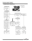
Blower Testing
Gas control power
switch
Yellow pressure
switch wires
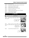
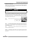
WARNING
115 volt potential exposure. Use caution making voltage checks to avoid
personal injury.
Control access
cover
28