


19
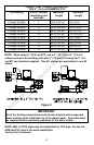
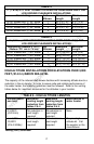
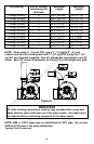
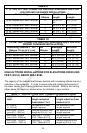
Terminating # of 90° Elbows
(excluding vent
terminal)
Maximum
Length
Minimum
Length
Through the Wall 0 105 ft (32.0 m) 10 ft (3.1 m)
Through the Wall 1 100 ft (30.5 m) 10 ft (3.1 m)
Through the Wall 2 95 ft (29.0 m) 10 ft (3.1 m)
Through the Wall 3 90 ft (27.5 m) 10 ft (3.1 m)
Through the Wall 4 85 ft (26.0 m) 10 ft (3.1 m)
Through the Wall 5 80 ft (24.4 m) 10 ft (3.1 m)
Through the Roof 0 55 ft (16.8 m) 5 ft (1.5 m)
Through the Roof 1 50 ft (15.3 m) 5 ft (1.5 m)
Through the Roof 2 45 ft (13.7 m) 5 ft (1.5 m)
Through the Roof 3 40 ft (12.2 m) 5 ft (1.5 m)
Through the Roof 4 35 ft (10.7 m) 5 ft (1.5 m)
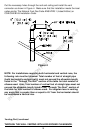
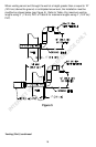
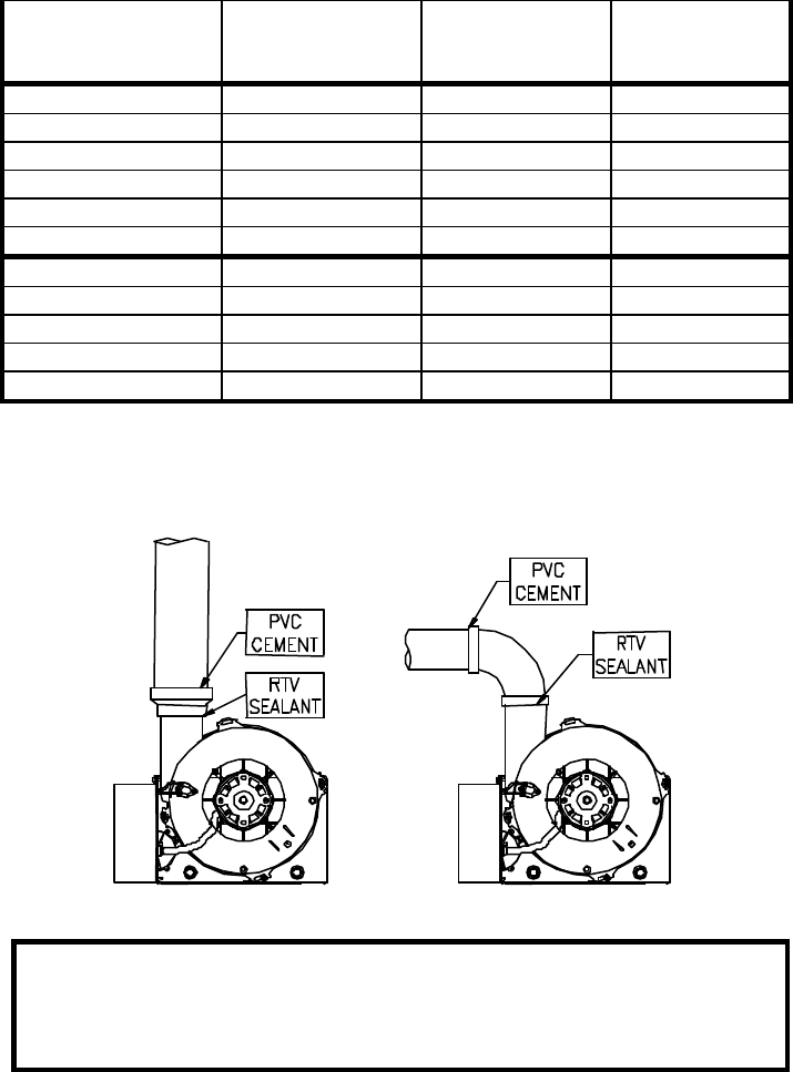
NOTE: When using 3” (7.6 cm) PVC, use a 3” (7.6 cm) to 2” (5.1 cm)
reducer and exit the building wall with 2” (5.1 cm) PVC using the 2” (5.1
cm) 45° vent terminal supplied. Two 45° elbows are equivalent to one 90°
elbow. Each 90° elbow is equivalent to 5 feet (1.5 m) of straight vent pipe.
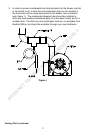
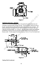
Figure 6
NOTE: ABS or CPVC pipes may be substituted for PVC pipe. Do not mix
ABS and PVC pipe in the same installation.
Venting (Part II) continued-
IMPORTANT
All of the Venting connections must be leak checked with a soap and
water solution upon initial start up of the water heater. Any leaks must
be repaired before continuing operation of the water heater.
INTERNET VERSION FOR REFERENCE ONLY