


17
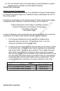
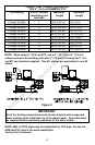
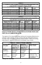
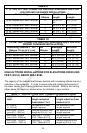
TABLE 4
3” (7.6 cm) PVC VENT CONNECTOR LENGTHS FROM INSIDE WALL FOR
LOW GROUND CLEARANCE INSTALLATIONS
Terminating # of
Elbows
Maximum
Length
Minimum
Length
(2) 90° Elbows with (1) 90° Elbow 1 30 ft (9.1 m) 5 ft (1.5 m)
(2) 90° Elbows with (1) 90° Elbow 2 25 ft (7.6 m) 6 ft (2 m)
(2) 90° Elbows with (1) 90° Elbow 3 20 ft (6.1 m) 8 ft (2.5 m)
(2) 90° Elbows with (1) 90° Elbow 4 15 ft (4.6 m) 10 ft (3 m)
TABLE 5
4” (10.2 cm) VENT CONNECTOR LENGTHS FROM INSIDE WALL FOR
LOW GROUND CLEARANCE INSTALLATIONS
Terminating (Reduce 4” to 3”)
(Reduce 10.1 cm to 7.6 cm)
#of
Elbows
Maximum
Length
Minimum
Length
(2) 90° Elbows with (1) 90° Elbow 1 60 ft (18.3 m) 10 ft (3 m)
(2) 90° Elbows with (1) 90° Elbow 2 55 ft (16.8 m) 12 ft (3.7 m)
(2) 90° Elbows with (1) 90° Elbow 3 50 ft (15.2 m) 15 ft (4.6 m)
(2) 90° Elbows with (1) 90° Elbow 4 45 ft (13.7 m) 18 ft (5.5 m)
(2) 90° Elbows with (1) 90° Elbow 5 40 ft (12.2 m) 22 ft (6.7 m)
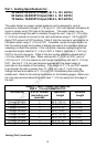
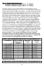
HIGH ALTITUDE INSTALLATIONS FOR ELEVATIONS OVER 3,000
FEET (914.5 m) ABOVE SEA LEVEL
The capacity of the induced draft blower declines with increasing altitude due to a
reduction in the air density. In order to assure safe and reliable performance of
the water heater, the following guidelines must be followed. Refer to the venting
tables below for maximum distances for the altitudes in your location.
TABLE 6 - HIGH ALTITUDE LENGTHS
Altitude above
sea level
Maximum
venting length
reduction from
tables 2 & 4
Maximum
venting length
reduction from
tables 3 & 5
Modifications to
water heater
0-3,000 ft
(0-914.5m)
No reduction in
vent length
required
No reduction in
vent length
required
None
over 3,000-
10,000 ft
(914.5-3048m)
No reduction in
vent length
required
No reduction in
vent length
required
Requires high
altitude kit. Call
the supplier or the
manufacturer
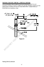
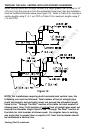
Venting (Part I) continued-
INTERNET VERSION FOR REFERENCE ONLY