


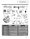
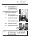
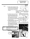
Step 6. Create the new mounting hole locations
for the new universal replacement blower.
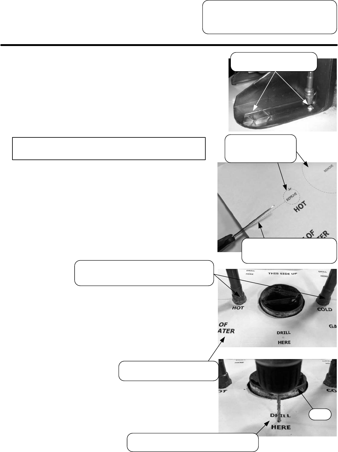
Use template supplied with manual.
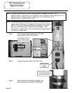
a.) On the template, P/N 238-47197-00,
the (3) circular sections for the water
connections and flue have already
been removed. Also, the dotted lines
from the side of the paper are
perforated for easy tearing.
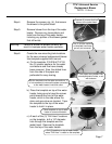
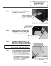
b.) Place the template on top of the water
heater, being sure to have the arrows
point towards the front of the water
heater, which is the side where the
drain and gas valve are located. Tape
the template to the top of the water
heater to hold it in place.
c.) At each of the (3) “Drill Here” locations
on the template, drill a 1/8” diameter
hole through the template and the
jacket head. Remove the template
from the top of the water heater.
Place template on top of water
heater in correct orientation.
Drill (3) locations on top of water heater,
where “Drill Here” is noted on the template.
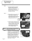
The (3) circular sections
on template have been
pre-cut and removed.
Warning: Failure to locate the blower correctly will
result in improper water heater operation.
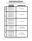
TTW1 Universal Service
Replacement Blower
MITW -10 Series
Page 7
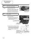
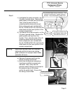
Slip the template over the water connections. It
is not necessary to remove the pipes connected
to the water heater’s inlet and outlet.
Tear paper along dotted lines
where perforation exists, or cut
with scissors.
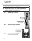
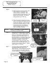
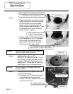
Unscrew (4) screws that hold
blower to the jacket head.
Step 4. Remove the screws, qty. (4), that secure
the blower to the jacket head.
Step 5. Remove blower from the top of the water
heater. Remove any loose debris and
tools from the top of the water heater,
including any portion of the blower gasket
that still exists.
Drill