


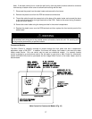
Note: If the cable cannot be run inside the wall cavity, then the plastic knockout should be removed
from the top or bottom of the control to allow flush mounting with the wall.
7. Disconnect the power from the water heater and remove the front cover.
8. Remove the plastic cover from the PCB and electrical connections.
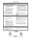
9. Thread the cable through the access hole at the base of the water heater and connect the wires
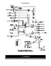
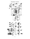
to the control terminals on the right hand side of the PCB. Refer to the control wiring illustration
at the end of this section.
10. Secure the control cable using the clamp provided in the control compartment.
11. Replace the plastic cover over the PCB terminals and then replace the front control panel of the
water heater.
WARNING
Do not attempt to connect the remote controls with the power on to the water heater. There is 120
volt terminals and wiring next to the remote control connections inside the unit. All servicing and
wiring must be performed by a qualified installer.
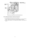
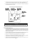
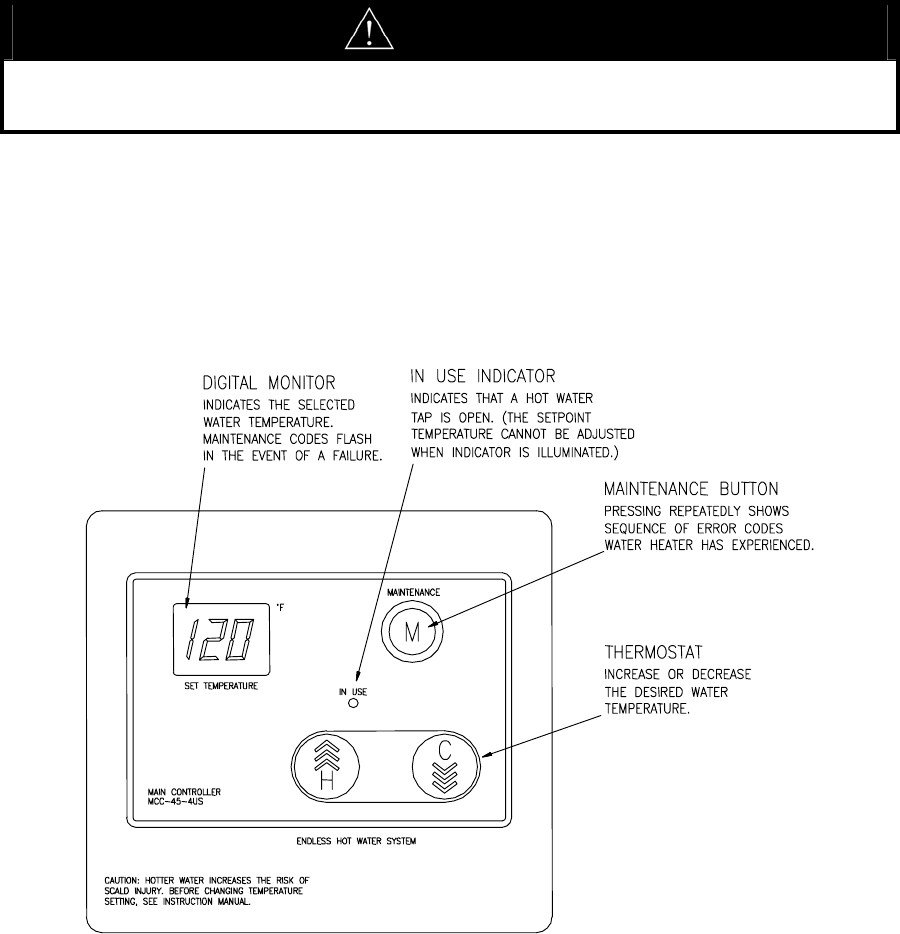
Commercial Models:
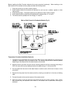
The Main Control is integrally mounted to project through the front panel and has a temperature
adjustment range of 96-180°F. In addition, the control will display fault codes in the event the water
heater needs service. Only one control may be used on commercial models. If a remotely located
control is desired in an area where most of the hot water is used, then a Main Control for commercial
models (239-44510-00) must be purchased and the integral Main Control on the water heater must be
disconnected.
Main Control for Commercial Models (Fig. 10)
37