


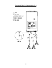
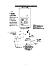
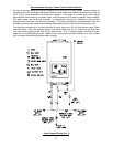
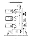
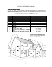
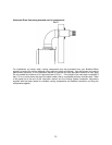
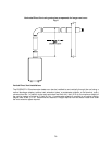
VENT/AIR INTAKE TERMINAL LOCATIONS
Direct Vent Terminal Location
Plan the vent system layout so that proper clearances are maintained from plumbing and wiring.
Before the vent is installed, determine the vent pipe termination location as shown below in the Vent
Terminal Location illustration.
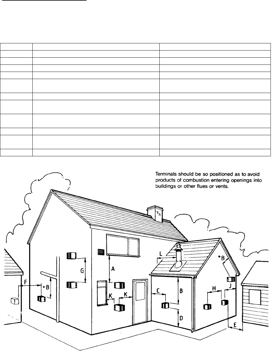
Vent/Air Intake Terminal Positions – MINIMUM Dimensions
Ref Description Distance in Inches (cm)
A Directly below an air opening or window 12” (30.5 cm)
B Below a gutter or eaves 36” (91.4 cm)
C From any internal corner 12” (30.5 cm)
D Above ground or the anticipated snow level 12” (30.5 cm)
E From an opposing wall or structure facing the
Terminal
24” (61 cm)
F From a Terminal facing a Terminal 48” (121.9 cm)
G Vertically between two Terminals on the
same wall
60” (152.4 cm)
H Horizontally between two Terminals on the
same wall
12” (30.5 cm)
J From any external corner 12” (30.5 cm)
K Horizontally from any air opening, window or
door.
12” (30.5 cm)
L Vertical Flue from wall (Flat or Pitched Roof) 24” (61 cm)
21