


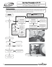
With flame sensor Disconnected
from ignition module, check
continuity to ground.
Is there continuity to ground?
N
Y
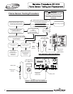
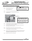
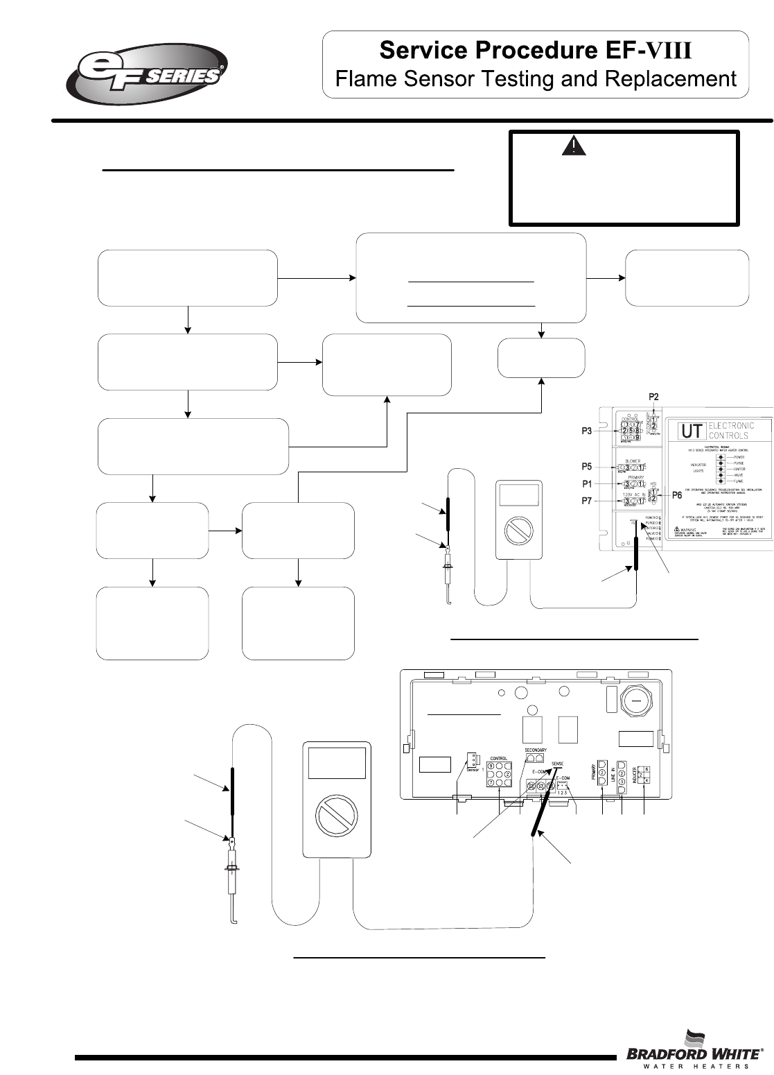
Flame Sensor Testing Procedure
Refer to illustration below, is there
a minimum of 1 micro amp during
1.5 second flame proving period?
Y
N
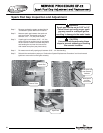
Is flame sensor free
of oxidation?
Clean or replace
flame sensor.
(see “Flame Sensor
Replacement
Procedure”)
N
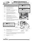
Is ceramic of flame
sensor cracked?
Replace flame sensor.
(see “Flame Sensor
Replacement
Procedure”)
Y
N
Flame sensing circuit OK
Y
Refer to ignition module/control board
illustration.(24 volts should maintain beyond the
1.5 second flame proving period.)
Hot Surface Ignition Models:
Is there 24 volts AC at locations P3(2) & P3(5)?
Direct Spark Ignition Models:
I
s there 24VAC between P5(5) and P5(8)?
Y
N
Call for
technical support
Replace flame sensor with
gasket
and/or wire lead.
(see “Flame Sensor
Replacement Procedure”)
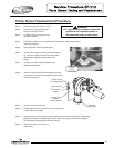
Remove flame sensor from water heater.
Check continuity from tip of flame sensor
to end of wire lead.
Is there continuity?
N
Y
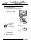
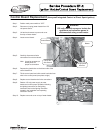
WARNING
120 volt potential exposure. Use caution
making voltage checks to avoid
p
ersonal injury. Flame sensor may be
too hot to handle, take necessary
precautions
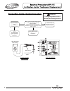
62
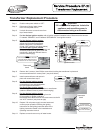
Flame
sensor
terminal
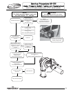
Volt meter set to
Micro amps setting
(µA)
Meter probe
Meter probe
Flame sensor
terminal on
control board.
Flame sensor
terminal
1
23
8
6
5
4
3
1
12
1
4
1
3
3
2
1
1
5
3
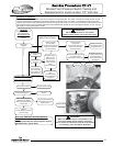
P2P4P5 P7P3
CONTROL BOARD
P10P9J1
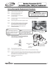
Volt meter set to
Micro amps setting
(µA)
Meter
probe
Meter
probe
Flame sensor
terminal on
ignition module.
HOT SURFACE IGNITION MODELS
DIRECT SPARK IGNITION MODELS
62