


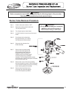
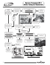
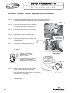

Exhaust Pressure Switch Replacement Procedure
Step 1. Position main power switch to “OFF” position.
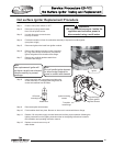
Step 2. Loosen adhesive backed rubber escutcheon from service panel access cover
and slide escutcheon back along exhaust pipe to allow for removal of cover.
Step 3. Remove screws from service panel access cover
(¼" nut driver) and remove cover from heater.
(see photos at right)
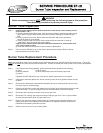
Step 4. Disconnect silicone tubing and wire leads from
pressure switch. (see photos at right)
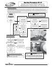
Step 5. Remove pressure switch mounting screws
(5/16" wrench) and remove pressure switch.
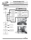
Step 6. Assemble new pressure switch to heater using
screws from step 5.
Step 7. Reconnect wire leads. Note: wire leads are
interchangeable with either terminal.
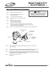
Step 8. Reconnect silicone tubing to pressure switch
as follows:
a) Exhaust pipe tubing connects to
negative (-) side of switch
identified by the (-) symbol
located on switch.
b) Exhaust collector tubing connects
to positive (+) side of switch
identified by the (+) symbol located
on the switch.
Step 10. Reinstall service panel access cover and
rubber escutcheon.
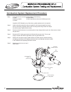
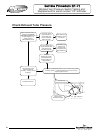
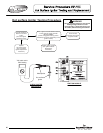
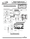
Exhaust Pressure Switch Testing and Replacement
For serial numbers prior to “CF”
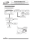
Step 9. Restore 120 volt power supply to water heater
and confirm proper operation following the
lighting instructions on the lighting instruction
label or the lighting instructions located in the installation
and operating instruction manual.
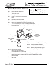
Exhaust pipe
pressure tap location
Exhaust collector
pressure tap location
(serial numbers prior
to “CF”)
Example of switch
showing positive
side identifier
56
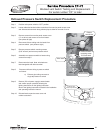
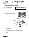
Rubber
escutcheon
Pressure switch
mounting screw
5/16 hex head
Silicone tubing
Wire leads
56