


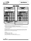
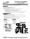
8
Power supply Dedicated 120 VAC, 60 Hz, 15A
Thermostat Sensor
11,900 Ohms @ 70°F, ECO opens @ 207°F Max., ECO close @ 120°F Min. Redundant
sensor for ECO. Sensor inside well for easy replacement of sensor.
Spark Rod Igniter 0.22" nominal gap to the burner surface.
Flame Sensor Output Minimum 1 micro amp, Typical range 5 to 30 micro amps.
Control Display
Digital display, 24 volts. Temperature Range: 70-180 deg. F. Used to set tank temperature
(deg. F or deg. C), show operating status, Display error codes, error code history, limit
maximum setpoint temperature.
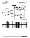
Control Board
Operates from 24 volt from transformer. Controls tank temperature, ignition functions,
combustion blower. See ignition timings in sequence of operation for Integrated Control.
Gas Valve Negative regulation, 24 VAC, ½" PSI max., 4.5" W.C. Minimum running inlet.
Transformer 120VAC primary, 24VAC secondary, 40VA.
Vent Safety Switch Normally closed, opens @ 350°F, manual reset.
Blower 120VAC, 60Hz, .6-1 amps, 6400 RPM.
Approved Gas Type Natural or Propane. Unit must match gas type supplied.
Venting System Power vent, balanced direct vent or unbalanced direct vent. See vent tables on page 7
Approved Vent Materials PVC or CPVC
Gas Supply
Minimum ¾" NPT
(
schedule 40 black iron pipe recommended)
Minimum Clearance
for Servicing
18" from top, 24" from front, 4" sides and rear.
Maximum Water Supply
Pressure
150 PSI
Gas Pressure (Nat & L.P.) 14.0" W.C. maximum static, 4.5" W.C. minimum running (recommend 7.0" W.C. min running)
Combustion Levels CO2: 10-11%, CO: less then 0.04 percent (400 PPM) air free
Blocked Vent Pressure
Switch
24VAC, normally closed, opens when pressure increases to +2.70 W.C.
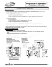
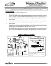
Serial Numbers including and AFTER GB13006174 and ALL EFR models
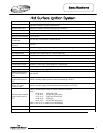
NOTICE:
THE EF100T399 MODEL SERIES DO NOT USE THE HONEYWELL
INTEGRATED CONTROL SYSTEM. THESE MODELS USE THE UT
ELECTRONICS CONTROL MODULE WITH HOT SURFACE IGNITION.
8