


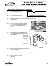

Flame Sensor Replacement Procedure
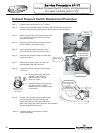
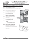
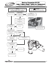
Step 4. Fold back insulation in front of combustion assembly to expose flame sensor.
(see photo at right)
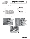
Step 5. Disconnect wire lead from flame sensor.
Step 6. Remove the 2 sensor mounting screws (magnetic
tip, long reach Phillips screw driver) and remove
flame sensor & gasket from transition base
flange.
Step 7. Remove any residual gasket material from
transition base flange.
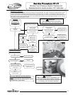
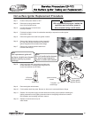
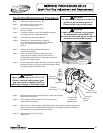
Step 9. Reconnect flame sensor wire.
Step 10. Fold insulation back into place. Be sure no wires are in
contact with burner flange.
Step 8. Install new flame sensor with new gasket provided
using screws from step 6. Arrange flame sensor with
hook towards burner.
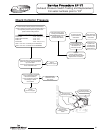
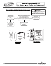
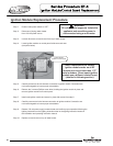
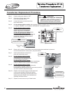
Step 1. Position main power switch to “OFF”
Step 2. Disconnect (unplug) water heater
from 120 volt power source.
Step 3. Un-latch & remove surround cover
from top of heater.
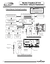
Step 11. Restore 120 volt power supply to water heater and confirm proper operation following the
lighting instructions on the lighting instruction label or the lighting instructions located in
the installation and operating instruction manual.
Step 12. Replace surround cover on top of
water heater.
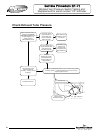
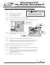
Transition
base flange
Flame sensor
mounting screws
Flame sensor
Flame sensor
gasket
Arrange hook
of sensor
towards burner
Flame
sensor
WARNING
120 volt potential exposure. Isolate the
appliance and reconfirm power is
disconnected using a multi-meter.
63
63