


PDX SERVICE PROCEDURE III
Pressure Switch Testing and
Replacement
Exhaust Pressure Switch
Testing
WARNING
120 volt potential exposure. Use caution
making voltage checks to avoid personal injury.
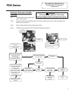
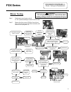
Step 1. Position power switch on gas control
to the “OFF” position.
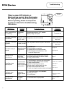
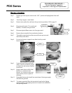
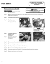
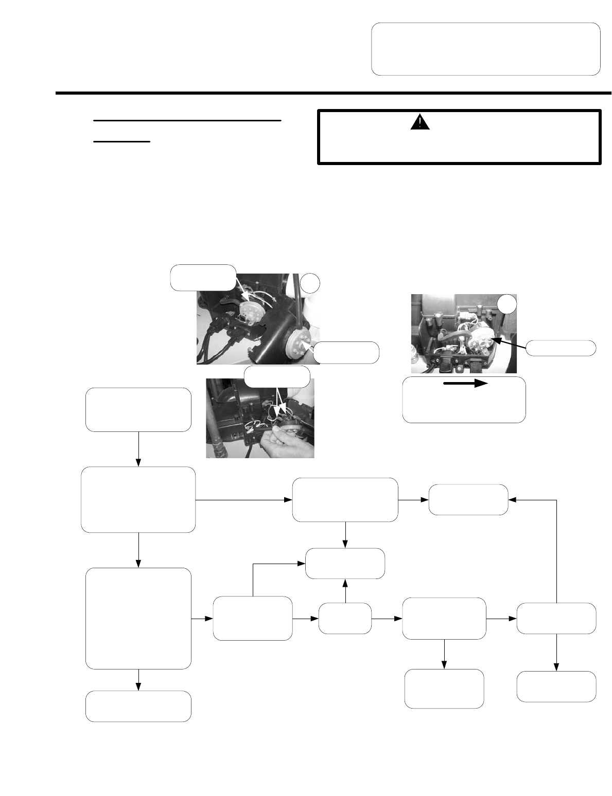
Step 2. Remove the three screws (Phillips screw driver) from control access cover on blower assembly and
remove cover (see photo 1).
Step 3. Remove tubing and wires from inlet pressure switch.
Step 4. Carefully remove pressure switch from blower housing (see photo 2)
2
Use a multi-meter set to the
ohms setting. With blower off,
check across pressure
switch terminals.
Are switch contacts open?
(no electricalcontinuity)
Check tubing and pressure
tap on switch for blockage.
Is there blockage?
Replace switch
(see page 18)
Position gas valve power
switch to the “ON” position
and adjust thermostat
to call for heat,
this will start the blower.
Check with multi-meter, do
pressure switch contacts
close with blower running
with the switch in the
vertical postition?
With steps 1,2,3 & 4
complete,
disconnect wire leads from
pressure switch.
Y
N
Y
N
Switch contacts are OK.
See safety circuit trace
(page 30)
Is vent
system
blocked
N
See blower testing
(page 21)
Is blower OK?
Clear blockage
Y
N
Y
N
Correct blower
problem.
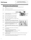
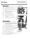
Pressure Switch
Slide pressure switch in direction
of arrow while tilting slightly away
from blower housing.
Is vent system length
within vent table
specifications
listed on page 7
Y
Reconfigure vent
system to be
compliant with
vent tables.
N
Y
Pressure switch
wire leads
Page 17
Check tubing and
pressure tap on
switch for blockage.
Is there blockage?
N
Y
PDX Series
1
E
xhaust
pressure switch
Inlet pressure
switch
17