


Page 49
COPPER BRUTE II (500 - 2000)
and boilers ordered with low temperature controls. To
replace the switch, shut off the 120-volt power to the
appliance. Remove the cover from the switch to access
the mounting screws. Remove the screws, and pull the
switch off the control panel. Remove the capilliary
and bulb from the thermal well located in the header.
Replace in reverse order.
7.2.6 Temperature Control
The temperature control is a Bradford White
LHSC. To replace the control, shut off the 120-volt
power to the appliance. Remove the cover from the
control panel, and remove the mounting screws to
remove the controller. Replace in reverse order.
7.2.7 Ignition Controls
The ignition controls ensure the proved
interrupted-type ignition system. They control the
hot surface ignitors and prove that the ame signal
is appropriate for powering the gas valves. It also
controls the blower’s pre-purge and post-purge.
Copper Brute II sizes 500 and 750 have one ignition
control. Sizes 1000 to 2000 have two ignition controls.
On sizes 1000, one ignition control controls stages 1
and 2, and the second ignition control controls stage 3.
On sizes 1250–2000, one ignition control is for stages
1 and 2, and the other is for stages 3 and 4.
To replace a control, shut off the 120-volt power
to the appliance. Remove the cover from the control
panel. Remove the electrical connectors from the
ignition control. Take out the controller’s mounting
screws, and pull the controller out. Replace in reverse
order.
7.2.8 Ignitors
The ignitors used are 120v “Hot Surface” type.
They are energized whenever there is a call for heat
and switched off when ignition is established and the
ame has been sensed. Copper Brute II sizes 500 and
750 have one ignitor. Sizes 1000 to 2000 have two
ignitors. To replace the ignitor, shut off the 120-volt
power to the appliance, remove the ignitor access
panel, disconnect the Molex connector, remove the
two mounting screws on the ignitor ange, and pull the
ignitor out. Install in reverse order, always using a new
ignitor gasket with the replacement ignitor.
Caution
Ignitor gets hot.
7.2.9 Ignition Sensors
The ignition sensors ensure that the main ame
is ignited, so that raw gas is not allowed to ll the
combustion chamber. Copper Brute II sizes 500 and
750 have one sensor. Sizes 1000 to 2000 have two
sensors (one for each ignition control). The ignitors
are the ignition sensors on Copper Brute II appliances.
There are no separate ignition sensors.
7.2.10 Transformer
The Copper Brute II’s transformer is not capable
of supplying control voltage for external devices such
as zone valves, which must have their own separate
power supply. Should a transformer need replacing,
shut off the 120-volt power. Unplug the transformer
wires, remove the mounting screws and remove the
transformer. Replace transformer in the reverse order.
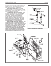
7.2.11 Blowers
The combustion air blowers bring the combustion
air for the Copper Brute II from the upper chamber to
the lower chamber. Mixing of the gas and air occurs
in the burners. Sizes 500, 750 and 1000 each have one
blower, and sizes 1250 to 2000 each have two blowers
(one blower for stages 1 and 2, and one for stages 3
and 4). If a blower change is required, turn off the
120-volt power and gas supply to the unit. Remove
the front panel. Disconnect the blower's wire harness.
Remove the screws at the blower ange, and pull the
blower out. Replace blower in reverse order, ensuring
that all joints are made correctly. After replacement,
ensure that the unit operates properly, by following the
set-up procedure in this manual.
7.2.12 Flow Switch
The Copper Brute II uses a paddle-type ow
switch to ensure that the unit has water ow before
ignition is allowed.
7.2.13 Heat Exchanger Coil
WARNING
Black carbon soot buildup on a dirty heat exchanger
can be ignited by a random spark or ame, thereby
creating a risk of re or explosion.. To prevent this
from happening, dampen the soot deposits with a
wet brush or ne water spray before servicing the
heat exchanger.
The Copper Brute II has a pre-mixed burner
system. These systems provide the burners with
sufcient air for complete combustion, and black
carbon sooting is seldom experienced. If sooting
is suspected, view ports for inspection of the heat
exchanger are provided on both sides of the boiler.
They are located below the headers, and are accessed
by opening the small round cover that is attached by
one screw. In the unlikely event that there is a buildup
of black carbon soot or other debris on the heat
exchanger, clean per the following:
1. Disconnect the electrical supply to the unit.
2. Turn off the gas supply by closing the manual gas
valve on the heater.
3. Disconnect and remove the wires, conduit and
sensors from all components that are attached to
the inlet/outlet header.
4. Isolate the heat exchanger from the water supply.
5. Disconnect header anges from inlet and outlet.