


Page 38
BRADFORD WHITE CORP.
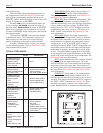
APPLICATION MODE SYSTEM
SETTING SENSORS USED
• Parallel piping (non-
primary/secondary)
hydronic system 1 • None
• DHW with or without
a tank aquastat
• Primary/secondary
hydronic system 2 • Bradford White System
(pref'd by Bradford White) Sensor (shipped
• No outdoor reset with each Copper Brute II)
• Parallel piping (non-
primary/secondary)
hydronic system 3 • Bradford White System
• DHW Sensor (shipped (with
• Advanced control each Copper Brute II)
capability
• No outdoor reset
• Parallel piping (non-reset • Bradford White outdoor
primary/secondary) sensor (optional
hydronic system 4 part #R2014000)
• Advanced control
capability
• Outdoor reset
• Primary/secondary • Bradford White System
hydronic system 5 Sensor (shipped
(preferred by with each
Bradford White) Copper Brute II)
• Outdoor reset • Bradford White outdoor
reset sensor (optional part
# R2014000)
• Building automation
control
• Multiple boiler system 6 • None
control
• Energy management
system
• Other external control
Table 11. Modes and Sensors for Applications.
contact the factory.
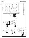
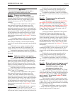
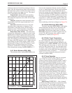
There are three black programming buttons on
the Temperature Control (see Figure 25). Press and
hold all three programming buttons until the word
ADJUST appears in the upper right corner of the LCD
display (it replaces the word VIEW).
Pressing
ITEM cycles you through the items you
need to program.
UP ARROW increases the value of
that item, while
DOWN ARROW decreases it. ADJUST
mode exits if you don’t press a button for 20 seconds.
To return to ADJUST mode, simply press and hold the
three buttons again.
The rst item is MODE; enter the mode number
as determined above. The Temperature Control will
then present you with some or all of the following
options, depending on the mode you have chosen:
In mode 6 (external boiler control), you will not
see the following options. Refer to Section 6.4.10 for
setup information for mode 6.
FOR ALL OTHER MODES:
BOIL MASS (Boiler Mass): Always choose “1”.
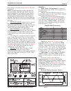
BOIL TARGET (Boiler Target Temperature):
Your desired set-point temperature. See Section 6.4.5
and Figure 26 for more information.
BOIL MIN (Boiler Minimum Temperature): This
setting tells the Temperature Control to maintain at
least this temperature, even if the PID logic determines
a lower setting would save energy. The BOIL MIN
should always be 120°F (49°C) or higher to prevent
condensation, and can be set up to 10°F below your
BOIL TARGET temperature. See Section 6.4.3 for
more information.
BOIL MAX (Boiler Maximum Temperature):
This setting tells the Temperature Control to limit the
maximum outlet temperature to this setting or below,
and determines how quickly the temperature control
“stages down” or off. If the BOIL MAX setting is
much higher than the BOIL TARGET temperature, the
temperature control will re all stages until the target
temperature is reached, and then shut down all stages
at once. To enable gradual staging down of the boiler
as you approach your target temperature, set the BOIL
MAX to the same setting as the target temperature. See
Section 6.4.4 for more information.
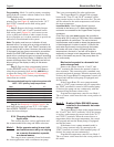
DIFF (Boiler Differential): This setting is divided
above and below the target temperature. The water
will be allowed to cool ½ this setting below the target
temperature before rst stage res, and will heat to ½
this setting above the target temperature before staging
the boiler down. See Section 6.4.1 and Figure 28 for
more information.
PUMP DLY (Pump Delay): On pump mounted
units, the boiler mounted pump continues to run for
the time selected after the heat demand in the system is
satised. This setting also affects the 24VAC output on
the “PMP” “PMP” terminals (see Section 5.2). These
terminals can power a contactor for a larger system
pump. Bradford White recommends a minimum pump
Figure 25. Temperature Control.