


XLA 3200 | Installation Manual |
Bosch Security Systems | January 2004
EN
|
11
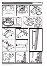
How to use these mounting method:
1.Determine the dimensions of the desired ‘listening area’
(a horizontal plane at the level of the listeners’ ears –
refer to the dashed line in figure 1).
2.Measure the maximum distance from loudspeaker
array to the last listener in the listening area
(corresponding to ‘B’ in figures 1, 2 and 3).
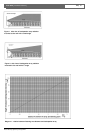
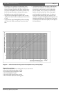
3.Refer to diagram 1, and trace upwards from the
maximum distance on the horizontal axis. From the
vertical intersection with diagonal B-line, you go
horizontal to the vertical axis. The X-value (height of
loudspeaker array mounting bracket above the listening
plane, ‘X’ in figure 1) is standing on this axis. The
horizontal intersections with other diagonal lines provide
information about the dimensions of the listening area.
These numbers are related to figures 2 and 3 (see also
example below).
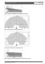
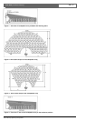
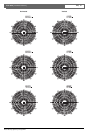
4.Figure 2 shows the 1kHz octave shape radiated by the
loudspeaker array and figure 3 shows the 4kHz octave
shape radiation. The listening area with the optimal
acoustic performance is in these shapes. Ensure the
4kHz shape with the dimensions obtained using
diagram 1 adequately covers the desired listening area.
5.If the desired listening area is covered by the 4kHz
shape, the X-value on the vertical axis show at what
height the loudspeaker array must be mounted above
the listening plane. Note that the loudspeaker array
must be mounted at an angle of 8
0
at the chosen height!
Now you can mount the loudspeaker array for optimal
acoustic performance.
Example:
The maximum distance from loudspeaker array to last
listener is 15m. Tracing upwards from the 15m point on
the horizontal axis of diagram 1 to the diagonal B-line
and then sidewards to the vertical axis, the intersections
with the other diagonal lines provide dimensions of the
listening planes. In this example:
F-line (listening plane side length of 4kHz) = 11.1m
C-line (listening plane length) = 11m
E-line (half width listening plane of 4kHz) = 9.3m
A-line (minimum distance to listening plane) = 3.9m
On the vertical axis, the X-value (the height between the
listening plane and loudspeaker array mounting bracket) is
1.8m.
Installation questions and answers:
• The desired listening area is too large and does not
fit in the 4kHz shape.
Try another loudspeaker array mounting height or use
more loudspeaker arrays to get a larger listening area.
• Why use an angle of 8
0
for the loudspeaker array?
The radiated shapes shown in figures 2 and 3 with the
dimensions in diagram 1 are only valid when the
loudspeaker array is mounted at an angle of 8
0
. Only
this situation provides constant sound pressure level
and frequency response (constant directivity) in the
listening area.
• Can I use the loudspeaker array with another angle?
You can use the loudspeaker arrays also with another
angle but you will not get the optimum acoustic
performance. For example, greater sound pressure level
variation will be audible in the listening area. The values
in diagram 1 are not valid for other angles. It is
recommended never to use an angle greater than 8
0
.
• The loudspeaker array cannot be mounted as high
as desired.
If not the height can be reached by limitation of the
ceiling for example, use an angle of less than 8
0
. Focus
the 0
0
-axis of the loudspeaker array to the desired
maximum position (see figure 4). Note that the table
in diagram 1 and shapes in figures 2 and 3 are not
valid for this situation. Check in the listening area if
the speech intelligibility is acceptable.
Background information:
• The shapes are defined in an anechoic environment.
In these shapes at anechoic conditions, you have a
maximum of 6dB sound pressure variation and much
less perceived frequency response variation. In areas
with normal or high reverberations, less sound
pressure level variation take place and the size of
shapes will be bigger. The perceived frequency
response in this shape will then be almost constant.
• When you go further then the maximum position of
the listening area (beyond the maximum distance
from the loudspeaker array) only the sound pressure
level will decrease. There is almost no tone height
variation. The decrease in sound pressure level
depends strongly on the reverberation of the room.
• When you move too close to the loudspeaker arrays
(less than the minimum distance from the
loudspeaker array) a lack of high tones will very soon
occur.
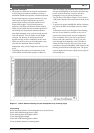
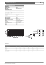
Listening area and related mounting height for XLA3201/00