


Page 2 © 2004 Bosch Security Systems MX938i Installation Instructions
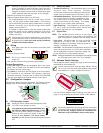
Hint: Mounting to removable ceiling tiles is not recommended
unless a sandwich is made of the base, ceiling tile and a
back plate behind the tile. Covers used for four-inch
octagonal and square boxes make a suitable back plate
(when used with bolts and wing nuts, as an example).
• Replace the enclosure on the base.
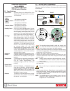
• Select an Optical Module (AR8-13 or AR13-18).
- For ceilings between 8 and 13 ft. (2.4 m and 4.0 m) from the
floor, use the optical module marked AR8-13. This marking
can be found next to the two optical module tabs. For ceilings
between 13 and 18 ft. (4.0 m and 5.5 m) high, use the optical
module marked AR13-18.
- To replace an optical module, push the optical module tabs
toward the center until the module snaps free of the circuit
board. Holding the new module by the tabs, snap the new
module into place.
Avoid fingerprints on the mirrored surfaces. If the mirrored
surfaces become soiled or otherwise marked, they can
be cleaned using a soft, clean cloth and any commonly
available mild window cleaner.
4.0 Wiring
Only apply power after all connections have been made
and inspected.
• Connect wiring as shown.
NOTE: Do not coil excess wiring
inside unit.
• Seal the Wire Entrance using the foam plug provided.
Terminal Descriptions
• 1 (B+) and 2 (B-): Connect to the Multiplex Bus of the control
panel. Use no smaller than #22 AWG (0.8 mm) wire between
the detector and the control panel.
• 3 (+) and 4 (-): Connect to the AUX Power of the control panel.
This connection is only required if LED operation (other than
during the walk test) is required. Use no smaller than #22 AWG
(0.8 mm) wire between the detector and the control panel.
5.0 Configuration Jumpers
Configure the detector using the appropriate Configuration Jumper
settings (refer to the following diagram for jumper locations).
Sensitivity
Jumper
Signal
Gain
Jumper
LED
Operation
Jumper
Address
Switches
(located under
the mirror)
5.1 LED Operation Jumper
• ON: Allows the LED to operate when activated by alarm.
• OFF: The LED will not operate on alarm.
If the detector is powered by the MUX Bus only,
the LED is for Walk Test purposes only. Disable
the LED when Walk Testing is complete. To
disable the LED, place the jumper in the OFF
position.If the detector has AUX Power
supplied, the LED operation may be left ON during normal
use.
5.2 Sensitivity Mode
• Standard Sensitivity: Recommended setting for
maximum false alarm immunity. Tolerates
environment extremes on this setting, but requires the
largest amount of intruder motion to achieve an alarm.
• Intermediate Sensitivity: Recommended setting for
any location where an intruder is expected to cover
only a small portion of the protected area. Tolerates
normal environments on this setting. This setting
will improve your intruder catch performance.
• High Sensitivity: Fast response to intruder signals.
For use in quiet environments where thermal and
illumination transients are not anticipated.
5.3 Signal Gain
NOTE: The MX938i permits selection of the signal gain
depending upon the environment to be protected. The
gain select jumper is located under the optical module.
• High Gain: Recommended for large coverage
applications up to 60 ft. (18.3 m) in diameter. The
MX938i is shipped in this setting. If the gain jumper is
missing, it will default to high gain.
• Low Gain: Recommended for applications where the
area to be covered is 40 ft. (12.2 m) or less in diameter
and for applications where the High Gain setting may
be too sensitive for environmental extremes.
NOTE: Setting the MX938i for the LOW Signal Gain setting reduces
the Coverage area to 40 ft. (12.2 m) in diameter.
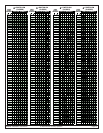
6.0 Address Switch Settings
• Set the address switch settings (see page 3) before connecting
the MX938i to the multiplex bus.
IMPORTANT
No two devices may be set to the same address. Having
two or more units set to the same address may prevent
fault detection or cause multiplex bus failure.
• You can find the Address Switch Settings using the chart on
page 3, or by calculating the decimal number of the address.
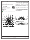
Binary Switch Values (Point 17 shown)
O
N
12345678
128 64 32 16 8 4 2 1
IMPORTANT
Zone (Point) Addresses 001 through 008 are reserved for
"on board" points on the DS7400(Xi) Series control panels.
Do not set any multiplex devices for Addresses 001-
008 when using a DS7400(Xi) Series control panel.
HI
LO
High Gain
HI
LO
Low Gain
ON
OFF
On
Off
ON
OFF
MUX
BUS
AUX
POWER
2134
-
IN
+
IN
B-
IN
B+
IN
Standard
S
I
H
Intermediate
S
I
H
High
S
I
H