


8
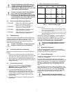
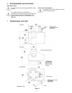
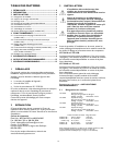
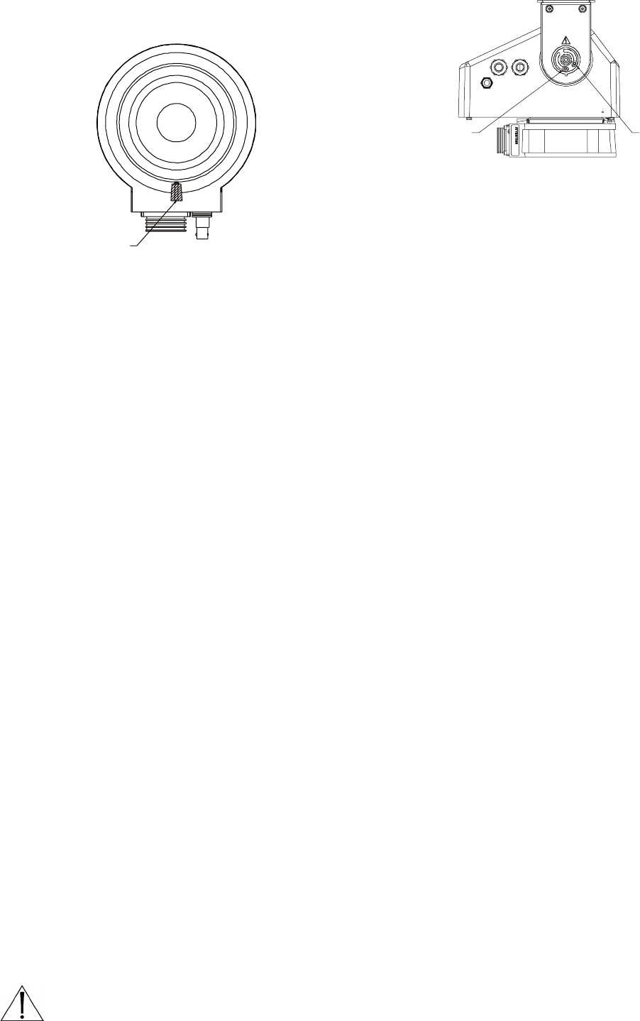
Front
Top View Of Base
Fixed Stop
(Red)
Pan Stops
Removed
Figure 4: Maximum Manual Pan and Maximum
Auto-Pan (345º Models)
4.3 Pan Stop Adjustment (345° Models)
1. Loosen the pan stops and adjust to the desired range for
manual pan and auto-pan. A recessed area in the pan
head allows enough clearance to remove a stop from the
base.
2. When all the stops are in place, check to see that they
are secure.
3. Operate the unit from the controller to confirm that the
limits are set properly. Readjust if required.
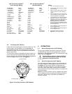
4.4 Pan Operation (360° Models)
These models allow 360 degree rotational (pan) operation.
They have no pan stops. These units can be manually panned
left or right or they can be panned continuously left or right
by auto-pan activation. Auto-Pan activation requires wiring
connections to pin 16 (Pan Left), pin 18 (Pan Right), and pin
19 (Common). See Figure 7.
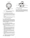
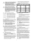
4.5 Tilt Stop Adjustment (All Models)
After the unit is installed and all wire connections are made,
apply proper power to the control unit. Refer to Figure 5.
and adjust the tilt stops as follows:
1. With the front of the pan/tilt facing you, remove the left
hub cap. The tilt stop adjustment screws are now
exposed.
2. Using the control unit, tilt the bracket up to the desired
position and stop the unit. Use the 3/32-inch Allen
wrench to loosen the Tilt Up stop. Slide the stop Up
until a faint click is heard (indicating switch actuation).
Tighten the Tilt Up limit stop screw.
3. Using the control unit, tilt the bracket to the desired
position and stop the unit. Use the 3/32-inch Allen
wrench to loosen the Tilt Down stop. Slide the stop
Down until a faint click is heard. Tighten the Tilt Down
limit stop screw.
4. Operate the control unit to verify proper tilt stop range
and operation. Repeat above sequence if necessary.
Make certain both tilt stop screws are snug. Replace the
hub cap.
Caution: Do not operate pan/tilt unit without
stops. Limit stops should not be adjusted
while unit is operating.
Tilt Up (CCW) StopTilt Down (CW) Stop
FRONTREAR
Figure 5: Tilt Stops (Side View - Plug Removed)
4.6 Pre-Position Models
The 345° models with pre-position capability require wiring
connections to pins 1 through 4, 8 and 9, and the use of a
controller or receiver/driver with the pre-position function.
Pan and tilt operation and limit stop adjustments, function the
same as the previous models described.