


7
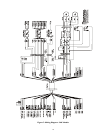
345° Pre-Position Models
5,6
Feed –through Wiring
Pin Number Color
1: PP Supply (+) Orange
2
2: Pan Position Yellow
2
3: PP Return (-) Gray
2
4: Tilt Position White/Black
2
5: Lens Common Green
2
6: Zoom Blue
2
7: Focus Violet
2
8: Zoom Position Brown
2
9: Focus Position Black
2
10. Accessory White
2,3
11. Accessory Red
2,3
12. Accessory Yellow
2,3
13: NC
1
14: NC
1
15: NC
1
16: Pan Left White
17: NC
1
18: Pan Right Violet
19: P/T Common Blue
20: Tilt Up Brown
21: Tilt Down White/Yellow
22: Ground Green/Yellow
2
23: Camera AC-Line Black
2,4
24: Camera AC-Neutral White
2,4
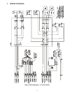
345° Pre-Position Models
5,6
Standard Wiring
Pin Number Color
1: PP Supply (+) Orange
2
2: Pan Position Yellow
2
3: PP Return (-) Gray
2
4: Tilt Position White/Black
2
5: NC
1
6: NC
1
7: NC
1
8: NC
1
9: NC
1
10. NC
1
11. NC
1
12. NC
1
13: NC
1
14: NC
1
15: NC
1
16: Pan Left White
17: NC
1
18: Pan Right Violet
19: P/T Common Blue
20: Tilt Up Brown
21: Tilt Down White/Yellow
22: Ground Green/Yellow
2
23: NC
1
24: NC
1
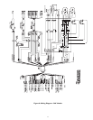
Notes
1. NC -- No Connection, do not use.
2. (Color Codes) indicate feed-thru wiring to
camera/housing.
3. Apply to 24 volt models only. Pins 10 thru
12 are not used in 110 volt or 220 volt
models.
4. (Color Codes) shown are for 24 volt and
110 volt models. For 220 volt models, color
codes are (23) Brown, and (24) Blue.
5. The conductors for pins 16 thru 24 (where
applicable) on 220 volt models should be
isolated from other wiring with reinforced
insulation requirements of DIN VDE
0860/05.89, IEC 65. The conductors for
pins 16 thru 24 (where applicable) must be
in HAR cord minimum cross sectional area
0.75 mm
2
(H05 VV-F).
6. Refer to Figure 6 under Wiring Diagrams
for the wiring schematic.
7. Refer to Figure 7 under Wiring Diagrams
for the wiring schematic.
8. Pre-Position models only. Refer to
Figure 8 for the wiring schematic.
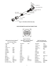
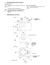
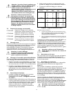
3.8 Pan Stops (345° Models)
Locate the three (3) limit stops on the base of the unit. The
red limit stop is the Fixed Stop. It is not adjustable and
should not be removed. The remaining two (2) stops
are
called the Pan Stops. These are positioned on each side of
the pan switch lever.
The two (2) pan stops are adjustable and secured with a set
screw. The screws can be accessed through the hole in the
end of each stop. Use a 3/32-inch Allen wrench (supplied) to
loosen and tighten the set screw. See Figure 3.
Rear
Top View Of Base
Front
Fixed Stop (Red)
Left
(CCW)
Right
(CW)
Pan
Stops
Figure 3: Pan Stop Locations (345º Models)
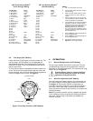
4 OPERATION
4.1 Manual Pan Operation (345° Models)
The pan stops establish the limits for manual pan. The two
(2) adjustable pan stops may be repositioned or removed
depending on the desired operation. The maximum pan range
setup is shown in Figure 4.
Caution: Never move or remove the fixed
stop. It must always be in place for proper
operation of the pan function.
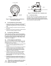
4.2 Auto-Pan Operation (345º Models)
Use of the auto-pan function requires wiring connections to
pin 16 (Pan Left), pin 18 (Pan Right), and pin 19 (Common).
See Figure 6. The auto-pan function is achieved by the
controller unit sensing changes in current flow through the
pan motor. When a pan stop is reached, the current flow
stops and internal circuitry of the controller unit reverses the
auto-pan direction.
Note: The pan/tilt controller must be equipped with special
current sensing circuitry to operate the auto-pan function in
this mode. The pan stops or the fixed stop establish the
limits for auto-pan.