


5
Caution: Do Not Exceed 30 VAC Input on
24 VAC models. Operation above 30 VAC
violates low voltage operation (Class 2
Specifications). Normal operation is 24 VAC.
CUL Approved 24 VAC Models.
Caution: Connect to Class 2 Power Supply
only. Total current through electrical
connector is 4 A maximum. Pan/tilt current
is 1 A maximum. Allowable camera/housing
is 3 A maximum. Use only 24 VAC cameras
and housings on feed-through models.
3.2 Recommended Mounting Equipment
LTC 9216/00
Medium duty wall mount designed to
support up to 45.3 kg (100 lb).
LTC 9222/00
Heavy duty wall mount designed to
support up to 90.6 kg (200 lb).
LTC 9214/00
Heavy duty 336 mm (14 inch) column
mount for ceiling or pedestal.
LTC 9224/00
Heavy duty 610 mm (24 inch) column
mount for ceiling or pedestal use.
3.3 Wall Mounting
Follow the instructions provided with mounts. Mount and
mounting surface must be able to support the weight of the
pan/tilt, camera/lens, and enclosure (if used). The
camera/lens/enclosure must be properly mounted and
balanced on the pan/tilt bracket.
Caution: The pan/tilts can only be mounted
upright or inverted; never horizontally.
3.4 Camera/Lens/Enclosure Mounting
Mount the camera/lens/enclosure to the pan/tilt bracket as
follows:
1. Balance the camera/lens/enclosure and adjust unit to
align with mounting holes. Fasten with a minimum of two
(2) 1/4-20 x 1/2-inch long fasteners and lock washers.
2. Make all electrical connections. Leave sufficient loops of
cable between camera/enclosure and pan/tilt to allow for
tilting and panning.
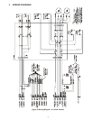
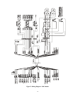
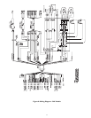
3.5 Electrical Connections
1. Cable must be wired according to Connector
Assembly (Section 3.7) and Recommended
Maximum Cable Lengths (Table 1).
2. Use separate shielded cables for camera power,
enclosure power, and pan/tilt control. If required,
combining lens control wiring and video coax within a
common cable is acceptable. The use of a common
multiconductor cable to combine all functions is not
recommended.
3. Use color coded conductors to aid wiring and future
identification.
4. Retain wiring diagram for later reference.
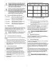
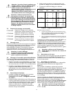
Model Wire Size Distance
1
Voltage Mm
2
AWG Feet Meters
24 VAC
2
0.5 20 140 43
1 18 230 70
1.5 16 360 110
2.5 14 590 180
4 12 940 287
110 VAC 0.5 20 2200 671
1 18 3500 1067
1.5 16 5500 1677
2.5 14 9000 2744
220 VAC 0.5 20 13400 4085
1 18 21200 6463
1.5 16 33300 10152
2.5 14 54400 16585
Table 1 Maximum Cable Lengths
Notes For Table 1
1. Values calculated at 20 ºC (68 ºF) using stranded tinned copper
wire, a common ground (neutral), and with both PAN and TILT
motors operating simultaneously.
2. For 24 VAC Models operating at or near -30º C, values are based
upon maintaining the supplied voltage within the voltage range as
specified in Section 3.1.
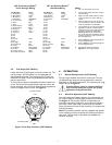
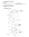
AMP Hand Crimping Tool #58495-1 is recommended for
crimping sockets. Refer to Figure 2 for the numbered
connector positions.The connector will accept up to a #16
AWG wire. If heavier gauge wire is required, pigtailing
according to local electrical codes is recommended.
Caution: Contact removal from connector
requires use of AMP #305183 extraction
tool.
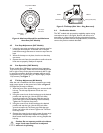
3.6 Grounding Connection
A ground screw is located on the base to the right of
connector. See Figure 8. Connect a 1 mm
2
(No.18 AWG)
ground wire to the nearest earth ground.
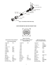
3.7 Connector Assembly
A mating connector, sockets and a strain relief are included
with the unit. See Figure 1.
To install, select the appropriate size strain relief clamp.
Choose one of the two strain relief clamps enclosed with the
sleeve and the extender. The clamping area is adjustable by
inverting or changing the strain relief clamps. Discard the
four strain reliefs on the carrier strip packaged with the
shield.
Insert the clamp into the strain relief until it bottoms. The
clamp should bottom on the wire bundle, not on the shield’s
shoulder. If the wire diameter is too small, temporarily
wrap the wire with electrical tape until proper clamping is
obtained. Secure the clamp with the two (2) screws
provided.
Caution: Make sure the wire bundle is
properly secured. Do NOT pinch the wires.