


EN
|
9
LTC 8785 Series | Instruction Manual | Operation
Bosch Security Systems | 19 April 2004
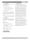
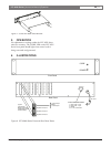
Figure 1 Cover and Rack Ears Removal
5OPERATION
No adjustments or settings within the LTC 8785 Series
units are necessary. The CODE LED on the LTC 8785
Series front panel should light when control code is
being converted and generated.
6ILLUSTRATIONS
S929A39AE
+
S
-
+
S
-
+
S
-
+
S
-
+
S
-
+
S
-
+
S
-
+
S
-
+
S
-
+
S
-
+
S
-
+
S
-
+
S
-
+
S
-
+
S
-
+
S
-
+
S
-
+
S
-
+
S
-
+
S
-
+
S
-
+
S
-
+
S
-
+
S
-
+
S
-
+
S
-
+
S
-
+
S
-
+
S
-
+
S
-
+
S
-
+
S
-
+
S
-
+
S
-
+
S
-
+
S
-
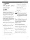
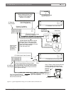
POWER
CODE
CODE IN
AC Cord
Front Panel
Rear Panel
Typical
Code Output
Mating Connector
(Removable Screw
Terminal Block)
+ Code Output
Shield
- Code Output
Duplicate of Above
Duplicate of Above
Duplicate of Above
9 Pin D Connector Pinouts
1 Data Code + Input
2 Data Code - Input
3 Shield
4to9 No Connection
S9511002AE
Figure 2 LTC 8785 Series Front and Rear Panel Views