


EN
|
8
LTC 8785 Series | Instruction Manual | Installation
Bosch Security Systems | 19 April 2004
4INSTALLATION
4.1 Power
Model No.
1
Rated Voltage Voltage Range Power
2
LTC 8785/60 120 VAC, 50/60 Hz 108 to 132 12 W
LTC 8785/50 220-240 VAC,50/60 Hz 198 to 264 12 W
1
These units may be supplied with grounded power cords;
grounding should not be defeated.
2
Nominal power at rated voltage.
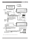
4.2 Procedure
Refer to ILLUSTRATIONS as necessary per the
following instructions.
If possible, install the LTC 8785 Series close enough to
the existing LTC 8568/00 Signal Distribution Unit
(or LTC 8569 Series Code Merger) so that the supplied
2 meter (6 ft) data cable will reach one of the outputs
of the LTC 8568/00 unit. The data output cables
corresponding to the older TC8561 Series
Receiver/drivers will need to be removed from the
existing LTC 8568/00 and connected to the outputs
of the LTC 8785 Series. The older LTC 8568/00
mating connector blocks can be connected directly to
the connectors on the rear panel of the new LTC 8785
Series. If necessary, the shielded-twisted pair cables
can be removed from the older connectors and wired
directly to the new connectors.
If these units are placed at a more distant location, the
data output cables for the receiver/drivers will need to
be extended or re-routed appropriately to the new site.
The data input to the LTC 8785 Series are made to the
9 pin D-connector on the rear panel. The supplied
data cable must be prepared so it can be used to
connect to an output of the existing LTC 8568/00
Signal Distribution Unit.
•Prepare the data cable by cutting off the end
of the cable containing the male 9-pin D-
connector.
• Locate the three conductors corresponding to
Data + (pin 1), Data - (pin 2), and Shield (pin
3).
• Strip the ends of the three conductors
approximately 6 to 7 mm (1/4 in) so they can be
connected to one of the output terminal blocks
of the existing LTC 8568/00 unit.
•Connect the conductor corresponding to pin 1
to a “+” terminal of the LTC 8568/00 output;
pin 2 connects to a “-” output, and pin 3 to a
“S” output. If necessary, a shielded-twisted pair
cable can be used to extend the data line
between an output of the LTC 8568/00 and the
input to the LTC 8785 Series.
• Install the AC power cord to the appropriate
power source. The POWER LED on the code
converter unit’s front panel should light when
power is applied.
4.3 Cover Removal
WARNING: Removal of the cover should only
be performed by qualified service personnel--
not user serviceable. The unit should always
be unplugged, before removing the cover and
remain unplugged while the cover is removed.
4.4 Mounting Options
4.4.1 Rack Mount
The units are supplied from the factory in an enclosure
suitable for rack mounting in an EIA 19-inch rack. The
enclosure is one EIA standard rack width (19 in) by
two rack units high (3 1/2 in). Peel off the four rubber
feet located on the bottom of the enclosure before
installing it into a console.
4.4.2 Desk Top Mount
If the unit is not going to be rack mounted, the
enclosure’s mounting ears should be removed. The
cover of the unit must be removed before access to the
mounting ears is possible. Removal of the cover should
only be performed by qualified service personnel. The
unit should always be disconnected from the AC
power source before removing the cover.
The top cover is fastened to the case by four screws
located on the rear of the unit. Once the screws have
been removed, the cover slides back and off the unit.
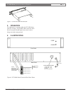
Remove each mounting ear by removing the screw
holding the mounting ear to the enclosure chassis. See
Figure 1.