


EN
|
8
Bosch Security Systems | 15 March 2004
LTC 8569 Series | Instruction Manual | Power Specifications
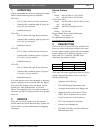
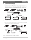
Two 2-meter (6 ft) data cables, for interface to Allegiant
main CPU bays, are supplied with the 2-channel
versions; four cables are supplied with the 4-channel
versions. These units can provide data to any device
capable of accepting biphase control code, including
the following:
•Allegiant Satellite systems
•AutoDome Series cameras
•Conventional Allegiant Receiver/Driver Series
• Allegiant LTC 8770 Relay Follower Series
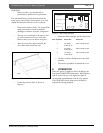
Control code wiring to the remote devices can be
connected to the outputs of the code mergers using
either star or daisy chain wiring configurations. Each
output is capable of driving up to eight (8) remote
devices using a daisy chain wiring configuration.
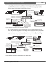
Multiple units may be cascaded to obtain additional
biphase code outputs.
The Code Merger units also provide an address offset
functionality. This feature is convenient when it is
necessary to convert camera address numbers,
encoded within the biphase data, to a higher value.
Offset increments of 16, 32, or 48 can be enabled via
an internal dip switch selection.
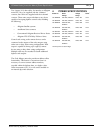
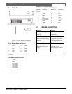
4POWER SPECIFICATION S
Model No. Rated Voltage Power
1
Voltage Range
LTC 8569/60 120 VAC, 50/60 Hz 108 to 132 12 W
LTC 8570/60 120 VAC, 50/60 Hz 108 to 132 12 W
LTC 8569/50 220-240 VAC, 198 to 264 12 W
50/60 Hz
LTC 8570/50 220-240 VAC, 198 to 264 12 W
50/60 Hz
LTC 8571/60 120 VAC, 50/60 Hz 108 to 132 12 W
LTC 8572/60 120 VAC, 50/60 Hz 108 to 132 12 W
LTC 8571/50 220-240 VAC, 198 to 264 12 W
50/60 Hz
LTC 8572/50 220-240 VAC, 198 to 264 12 W
50/60 Hz
1
Nominal power at rated voltage.