


LTC 2210 Series | Instruction Manual | Operatio
Bosch Security Systems | December 17, 2004
EN
|
7
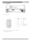
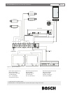
4.5 Alarm/Accessory Connector
A cable with a connector is supplied connecting to
alarm closures or other accessories.
The alarm output creates a short between the two
output pins (pins 9 and 14 Alarm Relay (NO)) when an
alarm occurs and open-circuits the pins when no
alarms are active (triggered). The alarm output has a
maximum carrying current of 1 A and a maximum
switching voltage of 40 V AC/DC. The alarm output
can be used to signal a VCR, lamp or relay.
The Alarm 1 (pin 6) is an open-collector output. It is
switched to ground when an alarm occurs (maximum
rating: 15 V, 30 mA).
The Remote Alarm Enable Input (pin 15) allows some
other security device, such as an access control system,
to enable the motion detector. The motion detector is
enabled when the Remote Alarm Enable Input is
switched to ground (<1 volt) and the Alarm Enable
option on the Main Menu is set to REMOTE. The
Remote Alarm Enable Input is disabled when the input
is not connected or the applied input voltage is greater
that 1 volt. The maximum input voltage that can be
applied is 15 volts.
Belden 8760 twisted shielded cable (or
equivalent) should be used for wiring to the
alarm connector and the total length of
unshielded cable should not exceed 10 cm
(3.9 in.) on each connector port to maintain
compliance with Directive 89/336/EEC.
4.6 Programming System Setup
Configuration options are provided through on-screen
menus. These menus are accessed by using the SETUP
key. With video present on the monitor, a momentary
press and release of the SETUP key will gain easy
access to the Main Programming Menu.
MAIN MENU VER 1.01
EXIT MENUS
ALARM ENABLE ON
ZONE SETUP
SYSTEM SETUP
DISPLAY
LANGUAGE ENGLISH
Select: ENTER
Exit Menu:ESC Scroll: ↓
The first line of each menu gives the menu name. The
main menu is the first menu displayed. In addition to
the menu name the first line of this menu also displays
the version number of the software in this product. All
programmable items are given in the lines immediately
below the menu name. The last two lines provide help
information.
5.0 OPERATION
5.1 Key Operations
MENU SCROLL: The ↑ or ↓ arrow keys are used to
scroll through menu items. The > character indicates
the currently selected menu item. The ↑ or ↓ arrow
keys are also used to program zone size and
placement.
ENTER: Pressing the ENTER key scrolls through the
options at current selected menu item.
CHANGE CURSOR POSITION: The ← or → arrow
keys are used to position zones and to program alarm
capture times.
EXITING A MENU: The ESC key or Previous Menu
option is used to exit to a previous menu. If the top
level menu is being displayed, pressing the ESC key or
selecting the Exit Menu option will exit from
Programming.
The Main Menu contains 5 settings. All of these
settings access sub-menus except for ALARM
ENABLE and LANGUAGE. If no key is pressed for a
period of 15 minutes, the menus will be automatically
exited.
5.2 Alarm Enable
This option is used to switch on the motion detector.
When Alarm Enable is ON, the product will detect
motion in the active zones defined for motion
detection (see Zone Setup). If motion is detected, all
alarm outputs will be switched on. When Alarm
Enable is set to REMOTE, the unit will detect motion
when the external remote alarm input is active (pin 15
of the Alarm Accessory Connector). The input is active
when it is switched to Ground.